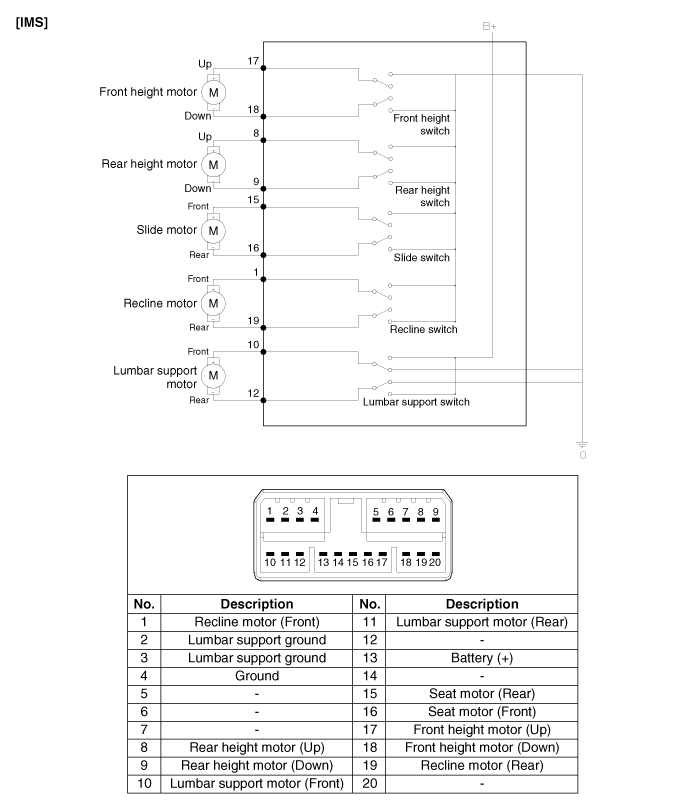
 Kia Forte: IMS Control Switch Circuit diagram
Second generation YD (2014-2018) / Kia Forte TD 2014-2018 Service Manual / Body Electrical System / IMS (Integrated Memory) / IMS Control Switch Circuit diagram

 IMS Power Seat Control Installation
-
Make sure that the IMS control switch connectors and related
connectors are plugged in ...
 IMS Control Switch Inspection
1.
With the power seat switch in each position, make sure that continuity
exists between the terminals below. If continuity is not as specified,
replace the power seat ...
See also:
Adjustment
Clutch Release Cylinder Air Bleeding
Procedure
•
Use the specified fluid. Avoi ...
Underdrive Brake Control Solenoid Valve(UD/B_VFS) Removal
Replacing an on/off solenoid valve (SS-A, SS-B) does not require
additional hydraulic pressure adjustment; however, the ...
Components Location
1. Converter housing
2. Automatic transaxle upper mounting bolt
3. Shift cable bracket
4. Manual control lever
5. Rear cover
6. Oil cooler tube
7. Oil level plug
8. Val ...
Copyright © www.kifomanual.com 2014-2024
