 Kia Forte: Cruise Control Switch Inspection
Second generation YD (2014-2018) / Kia Forte TD 2014-2018 Service Manual / Engine Electrical System / Cruise Control System / Cruise Control Switch Inspection
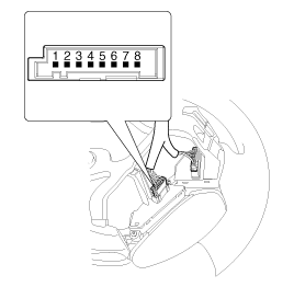
[Measuring Resistance]
| 1. |
Check for resistance between terminals in each switch position.
|
[Measuring Voltage]
| 1. |
Connect the cruise control switch connector to the control switch.
|
| 2. |
Measure voltage between terminals on the harness side connector
when each function switch is ON (switch is depressed).
|
| 3. |
If not within specification, inspect the control switch resistance.
The measuring resistance value is not within specification, replace
the switch and measure the voltage again.
|
| 4. |
If resistance is OK but, measuring voltage is not within specification,
inspect the wiring harness and connectors between the switch and the
ECM.
|

 Cruise Control Switch Removal
1.
Disconnect the negative (-) battery terminal.
2.
Remove the driver airbag module.
(Refer to Restraint - "Driver Airbag (DAB) Mod ...
See also:
Variable Charge Motion Actuator (VCMA) Inspection
1.
Turn ignition switch OFF.
2.
Disconnect the VCMA connector.
3.
Check that the VCMA is not stuck by foreign ...
Torque Converter Control Solenoid Valve (T/CON_VFS) Description
Torque converter control solenoid valve (T/CON_VFS) is attached to the
valve body. This variable force solenoid valve directly controls the hydraulic
pressure inside the torque converter.
...
Removal
1.
Separate the push rod (C) after remove the pin (A) and washer
(B).
2.
Remove the battery.
(Refer to Engine Electrical S ...
Categories
- Home
- Kia Forte BD 2019-2026 Owners Manual
- Kia Forte BD 2019-2026 Service Manual
- First Generation
- Second generation
- Kia Forte TD 2014-2018 Owners Manual
- Kia Forte TD 2014-2018 Service Manual

Copyright ® www.kifomanual.com 2014-2026