 Kia Forte: Telemetics Unit (TMU) Component
Second generation YD (2014-2018) / Kia Forte TD 2014-2018 Service Manual / Body Electrical System / MTS System / Telemetics Unit (TMU) Component
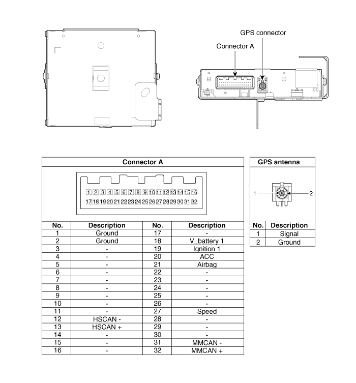
Connector Pin Specification
| No. |
Pin Name |
Type |
From |
To |
Description (Wiring
Spec.) |
| 1 |
GND |
DC Ground |
TMU |
Battery |
Connected to battery ground |
| 2 |
GND |
DC Ground |
TMU |
Battery |
Connected to battery ground |
| 3 |
- |
- |
- |
- |
- |
| 4 |
- |
- |
- |
- |
- |
| 5 |
- |
- |
- |
- |
- |
| 6 |
- |
- |
- |
- |
- |
| 7 |
- |
- |
- |
- |
- |
| 8 |
- |
- |
- |
- |
- |
| 9 |
- |
- |
- |
- |
- |
| 10 |
- |
- |
- |
- |
- |
| 11 |
- |
- |
- |
- |
- |
| 12 |
HS CAN (-) |
Data I/O |
BUS |
BUS |
High Speed CAN bus low |
| 13 |
HS CAN (+) |
Data I/O |
BUS |
BUS |
High Speed CAN bus high |
| 14 |
- |
- |
- |
- |
- |
| 15 |
- |
- |
- |
- |
- |
| 16 |
- |
- |
- |
- |
- |
| 17 |
- |
- |
- |
- |
- |
| 18 |
V battery 1 |
DC Input |
Battery |
TMU |
DC level input from battery Supply power to TMU |
| 19 |
Ignition 1 |
Data Input |
Junction Box |
TMU |
Vehicle Key mode status |
| 20 |
ACC |
Data Input |
Junction Box |
TMU |
Vehicle Key mode status |
| 21 |
Airbag |
Data Input |
ACU |
TMU |
Airbag status data from ACU |
| 22 |
- |
- |
- |
- |
- |
| 23 |
- |
- |
- |
- |
- |
| 24 |
- |
- |
- |
- |
- |
| 25 |
- |
- |
- |
- |
- |
| 26 |
- |
- |
- |
- |
- |
| 27 |
Speed |
Data Input |
- |
TMU |
GPS Calibration (UVO ONLY) |
| 28 |
- |
- |
- |
- |
- |
| 29 |
- |
- |
- |
- |
- |
| 30 |
- |
- |
- |
- |
- |
| 31 |
MM CAN (-) |
Data I/O |
BUS |
BUS |
Low Speed CAN bus low |
| 32 |
MM CAN (+) |
Data I/O |
BUS |
BUS |
Low Speed CAN bus high |
 Description
The Vehicle Information System is a Telematics service that ensures comfortable
and enjoyable driving by providing safety, security, and vehicle diagnostic
information, with the option of usi ...
 Telemetics Unit (TMU) Removal
1.
Disconnect the negative (-) battery terminal.
2.
Remove the glove box housing.
(Refer to Body - "Glove Box Housing")
...
See also:
Battery Installation
1.
Install in the reverse order of removal.
Battery (-)terminal installation:
4.0 ~ 6.0 N.m (0.4 ~ 0.6 kgf.m, 3.0 ~ 4.4 lb-ft)
...
Output Speed Sensor Circuit Diagram
...
Overhead Console Lamp Inspection
1.
Remove the overhead console lamp assembly then check for continuity
between terminals. If the continuity is not as specified, replace the
map lamp switch.
...
Categories
- Home
- Kia Forte BD 2019-2026 Owners Manual
- Kia Forte BD 2019-2026 Service Manual
- First Generation
- Second generation
- Kia Forte TD 2014-2018 Owners Manual
- Kia Forte TD 2014-2018 Service Manual

Copyright ® www.kifomanual.com 2014-2026