 Kia Forte: IMS Power Seat Control Inspection
Second generation YD (2014-2018) / Kia Forte TD 2014-2018 Service Manual / Body Electrical System / IMS (Integrated Memory) / IMS Power Seat Control Inspection
| 1. |
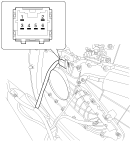
Disconnect the IMS control switch connector.
|
| 2. |
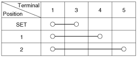
With the power IMS control switch in each position, make sure
that continuity exists between the terminals below. If continuity is
not as specified, replace the IMS control switch.
|
 IMS Power Seat Control Removal
1.
Disconnect the negative (-) battery terminal.
2.
Remove the front door trim.
(Refer to Body - "Front Door Trim")
...
See also:
Audio Unit Components
Connector Pin Information
No.
Connector A
Connector B
1
Rear left speaker (+)
-
2
Front left speaker (+)
-
...
[CVVT System Mode]
(1) Low Speed / Low Load
(2) Part Load
(3) Low Speed / High Load
(4) High Speed / High Load
...
Piston and Connecting Rod Inspection
Connecting Rod
1.
Check the connecting rod side clearance.
Using a feeler gauge, measure the end play while moving the connecting
rod back and forth.
...
Copyright © www.kifomanual.com 2014-2025


