
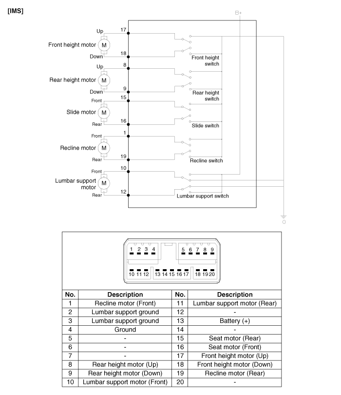
 Kia Forte: IMS Control Switch Circuit diagram
Second generation YD (2014-2018) / Kia Forte TD 2014-2018 Service Manual / Body Electrical System / IMS (Integrated Memory) / IMS Control Switch Circuit diagram
 IMS Power Seat Control Installation
-
Make sure that the IMS control switch connectors and related
connectors are plugged in ...
 IMS Control Switch Inspection
1.
With the power seat switch in each position, make sure that continuity
exists between the terminals below. If continuity is not as specified,
replace the power seat ...
See also:
Dynamic Damper Components
1. BJ assembly
2. Circlip
3. BJ boot band
4. BJ boot
5. Dynamic damper band
6. Dynamic damper
7. Shaft
8. TJ boot band
9. TJ boot
10. Spider assembly
1 ...
Side air bag
Your vehicle is equipped with a side air bag in each front seat.
The purpose of the air bag is to provide the vehicle's driver and/or the front
passenger with additional protection than that ...
Fuel Pump Motor Installation
1.
Install in the reverse order of removal.
...
Categories
- Home
- Kia Forte BD 2019-2026 Owners Manual
- Kia Forte BD 2019-2026 Service Manual
- First Generation
- Second generation
- Kia Forte TD 2014-2018 Owners Manual
- Kia Forte TD 2014-2018 Service Manual

Copyright � www.kifomanual.com 2014-2026