 Kia Forte: Relay Box (Passenger Compartment) Removal
Second generation YD (2014-2018) / Kia Forte TD 2014-2018 Service Manual / Body Electrical System / Fuses And Relays / Relay Box (Passenger Compartment) Removal
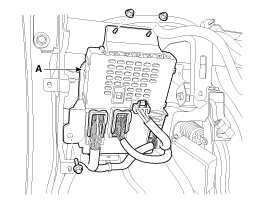
Passenger Compartment Junction Box (SJB)
| 1. |
Disconnect the negative(-) battery terminal.
|
| 2. |
Remove the crash pad lower panel.
(Refer Body - "Crash Pad Lower Panel")
|
| 3. |
Disconnect the connectors from the fuse side of the smart junction
box.
|
| 4. |
Remove the smart junction box after loosening the mounting nuts
(2EA) and bolt.
|
| 5. |
Disconnect the connectors from the back side of the smart junction
box.
|
 Relay Box (Passenger Compartment) Inspection
1.
The SJB can be diagnosed by using the GDS. The SJB communicates
with the GDS which then displays inputs and outputs along with codes.
2.
...
 Relay Box (Passenger Compartment) Installation
1.
Install the smart junction box.
2.
Install the crash pad lower panel.
3.
Check that all system operates norm ...
Copyright ® www.kifomanual.com 2014-2026

