 Kia Forte: Power Window Switch Inspection
Second generation YD (2014-2018) / Kia Forte TD 2014-2018 Service Manual / Body Electrical System / Power Windows / Power Window Switch Inspection
Power Window Main Switch Inspection
| 1. |
Disconnect the negative (-) battery terminal.
|
| 2. |
Remove the front door trim.
(Refer to Body - "Front Door Trim")
|
| 3. |
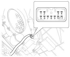
Disconnect the connector from the power window switch module.
|

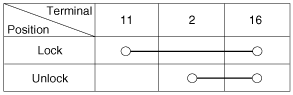
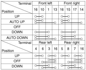
| 4. |
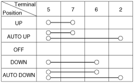
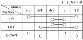
Check for continuity between the terminals in each switch position
according to the table.
[Driver/Passenger Safety]
[Driver Auto Down]
|
| 5. |
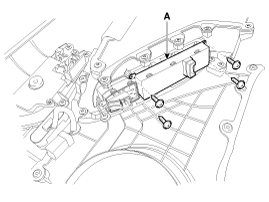
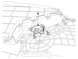
Remove the power window switch(A) after loosening the screws.
|
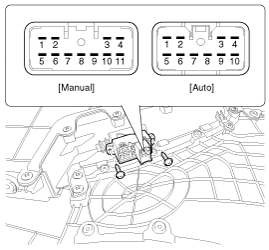
Passenger Power Window Switch Inspection
| 1. |
Disconnect the negative (-) battery terminal.
|
| 2. |
Remove the front door trim panel.
(Refer to Body - "Front Door Trim")
|
| 3. |
Disconnect the connector from the switch.
|
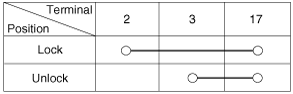
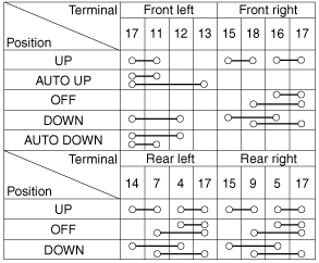
| 4. |
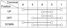
Check for continuity between the terminals in each switch position
according to the table. If the continuity condition is not normal, replace
the switch.
[Auto]
[Manual]
|
| 5. |
Remove the power window switch(A) after loosening the screws.
|
Rear Power Window Switch Inspection
| 1. |
Disconnect the negative (-) battery terminal.
|
| 2. |
Remove the rear door trim panel.
(Refer to Body - "Rear Door Trim")
|
| 3. |
Disconnect the 8P connector from the switch.
|
| 4. |
Check for continuity between the terminals in each switch position
according to the table. If the continuity condition is not normal, replace
the switch.
|
| 5. |
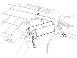
Remove the power window switch(A) after loosening the screws.
|
 Power Window Switch Circuit Diagram
Driver Power Window Switch
[Driver/Passenger Safety]
[Driver Auto Down]
Passenger Power Window Switch
Rear Power Window Switch
...
 Power Window Relay Inspection
Diagnosis With GDS
1.
It will be able to diagnose defects of power window with GDS quickly.
GDS can operates actuator forcefully, input/output value monitoring
and ...
Categories
- Home
- Kia Forte BD 2019-2026 Owners Manual
- Kia Forte BD 2019-2026 Service Manual
- First Generation
- Second generation
- Kia Forte TD 2014-2018 Owners Manual
- Kia Forte TD 2014-2018 Service Manual

Copyright ® www.kifomanual.com 2014-2026