 Kia Forte: Windshield Wiper-Washer Switch Removal
Second generation YD (2014-2018) / Kia Forte TD 2014-2018 Service Manual / Body Electrical System / Windshield Wiper/Washer / Windshield Wiper-Washer Switch Removal
| 1. |
Disconnect the negative (-) battery terminal.
|
| 2. |
Remove the steering wheel.
(Refer to Steering System - "Steering Wheel")
|
| 3. |
Remove the steering column upper and lower shrouds.
(Refer to Body - "Steering Column Shroud Panel")
|
| 4. |
Remove the clock spring.
(Refer to Restraint - "Driver Airbag (DAB) Module and Clock Spring")
|
| 5. |
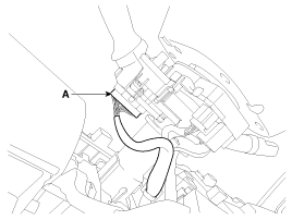
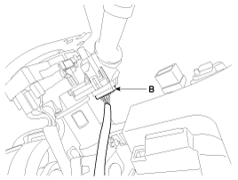
Disconnect the light switch connector (A) and the wiper switch
connector (B).
|
| 6. |
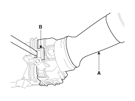
Remove the wiper switch (A) by pushing the lock pin (B).
|
| 7. |
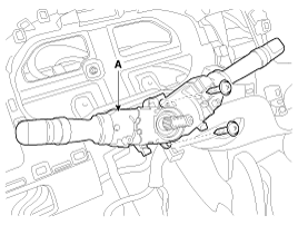
Loosen the screws (2EA) from the multifunction switch assembly
(A).
|
 Windshield Wiper-Washer Switch Inspection
Check for continuity between the terminals while operating the wiper and
washer switch. If it is not normal condition, replace wiper and wiper switch.
Wiper Switch
Washer Switch
...
 Windshield Wiper-Washer Switch Installation
1.
Install the multifunction switch.
2.
Install the clock spring.
3.
Install the steering column upper and lowe ...
See also:
Component Location
1. Cowl top cover
...
Compressor Oil Specification
1.
The R-134a system requires synthetic compressor oil (PAG) whereas
the R-12 system requires mineral compressor oil. The two oils must never
be mixed.
...
Starter Cleaning
1.
Do not immerse parts in cleaning solvent.
Immersing the yoke assembly and/or armature will damage the insulation
wipe these parts with a cloth only.
...
Copyright ® www.kifomanual.com 2014-2026


