 Kia Forte: ECM Terminal And Input/Output signal (A/T)
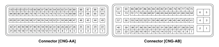
Second generation YD (2014-2018) / Kia Forte TD 2014-2018 Service Manual / Engine Control / Fuel System / Engine Control System / ECM Terminal And Input/Output signal (A/T)
| ECM Terminal Function |
Connector [CNG-AA]
| Pin No. |
Description |
Connected to |
| 1 |
Ignition Coil (Cylinder #2) control output |
Ignition Coil (Cylinder #2) [Without Immobilizer] |
| Ignition Coil (Cylinder #3) control output |
Ignition Coil (Cylinder #3) [With Immobilizer] |
|
| 2 |
- |
|
| 3 |
- |
|
| 4 |
- |
|
| 5 |
- |
|
| 6 |
- |
|
| 7 |
- |
|
| 8 |
- |
|
| 9 |
- |
|
| 10 |
- |
|
| 11 |
Camshaft Position Sensor (CMPS) [Bank 1/Intake] signal input |
Camshaft Position Sensor (CMPS) [Bank 1/Intake] |
| 12 |
Sensor power (+5V) |
Variable Charge Motion Actuator (VCMA) |
| Battery Sensor |
||
| 13 |
- |
|
| 14 |
Heated Oxygen Sensor (HO2S) [Bank 1/Sensor 2] signal input |
Heated Oxygen Sensor (HO2S) [Bank 1/Sensor 2] |
| 15 |
- |
|
| 16 |
Sensor feedback signal input |
Variable Charge Motion Actuator (VCMA) |
| 17 |
- |
|
| 18 |
- |
|
| 19 |
- |
|
| 20 |
Sensor ground |
Crankshaft Position Sensor (CKPS) |
| 21 |
Motor [-] control output |
Variable Charge Motion Actuator (VCMA) |
| 22 |
Ignition Coil (Cylinder #4) control output |
Ignition Coil (Cylinder #4) [Without Immobilizer] |
| Ignition Coil (Cylinder #1) control output |
Ignition Coil (Cylinder #1) [With Immobilizer] |
|
| 23 |
- |
|
| 24 |
- |
|
| 25 |
- |
|
| 26 |
- |
|
| 27 |
- |
|
| 28 |
- |
|
| 29 |
- |
|
| 30 |
Sensor ground |
Camshaft Position Sensor (CMPS) [Bank 1/Exhaust] |
| 31 |
Camshaft Position Sensor (CMPS) [Bank 1/Exhaust] signal input |
Camshaft Position Sensor (CMPS) [Bank 1/Exhaust] |
| 32 |
Sensor ground |
Camshaft Position Sensor (CMPS) [Bank 1/Intake] |
| 33 |
Sensor power (+5V) |
Throttle Position Sensor (TPS) 1,2 |
| 34 |
- |
|
| 35 |
Sensor ground |
Heated Oxygen Sensor (HO2S) [Bank 1/Sensor 2] |
| 36 |
- |
|
| 37 |
Sensor ground |
Variable Charge Motion Actuator (VCMA) |
| 38 |
- |
|
| 39 |
- |
|
| 40 |
- |
|
| 41 |
Crankshaft Position Sensor (CKPS) signal input |
Crankshaft Position Sensor (CKPS) |
| 42 |
Motor [+] control output |
Variable Charge Motion Actuator (VCMA) |
| 43 |
- |
|
| 44 |
- |
|
| 45 |
- |
|
| 46 |
- |
|
| 47 |
- |
|
| 48 |
- |
|
| 49 |
- |
|
| 50 |
- |
|
| 51 |
- |
|
| 52 |
- |
|
| 53 |
- |
|
| 54 |
Sensor ground |
Throttle Position Sensor (TPS) 1, 2 |
| 55 |
- |
|
| 56 |
Sensor shield ground |
Knock Sensor (KS) |
| 57 |
Immobilizer communication line |
Immobilizer control module |
| 58 |
Sensor ground |
Battery Sensor |
| 59 |
Intake Air Temperature Sensor (IATS) signal input |
Intake Air Temperature Sensor (IATS) |
| 60 |
- |
|
| 61 |
Sensor ground |
Manifold Absolute Pressure Sensor (MAPS) |
| 62 |
Sensor ground |
Engine Coolant Temperature Sensor (ECTS) |
| 63 |
Engine Coolant Temperature Sensor (ECTS) signal input |
Engine Coolant Temperature Sensor (ECTS) |
| 64 |
Ignition Coil (Cylinder #3) control output |
Ignition Coil (Cylinder #3) [Without Immobilizer] |
| Ignition Coil (Cylinder #2) control output |
Ignition Coil (Cylinder #2) [With Immobilizer] |
|
| 65 |
- |
|
| 66 |
- |
|
| 67 |
- |
|
| 68 |
- |
|
| 69 |
- |
|
| 70 |
- |
|
| 71 |
- |
|
| 72 |
- |
|
| 73 |
- |
|
| 74 |
- |
|
| 75 |
Throttle Position Sensor (TPS) 2 signal input |
Throttle Position Sensor (TPS) 2 |
| 76 |
- |
|
| 77 |
Sensor ground |
Knock Sensor (KS) |
| 78 |
- |
|
| 79 |
Battery Sensor signal |
Battery Sensor |
| 80 |
- |
|
| 81 |
- |
|
| 82 |
Manifold Absolute Pressure Sensor (MAPS) signal input
|
Manifold Absolute Pressure Sensor (MAPS) |
| 83 |
VIP (Current Pump) |
Heated Oxygen Sensor [Bank 1/Sensor 1] |
| 84 |
VG (Virtual Ground) |
Heated Oxygen Sensor [Bank 1/Sensor 1] |
| 85 |
Ignition Coil (Cylinder #1) control output |
Ignition Coil (Cylinder #1) [Without Immobilizer] |
| Ignition Coil (Cylinder #4) control output |
Ignition Coil (Cylinder #4) [With Immobilizer] |
|
| 86 |
- |
|
| 87 |
- |
|
| 88 |
- |
|
| 89 |
- |
|
| 90 |
- |
|
| 91 |
- |
|
| 92 |
- |
|
| 93 |
- |
|
| 94 |
- |
|
| 95 |
- |
|
| 96 |
Throttle Position Sensor (TPS) 1 signal input |
Throttle Position Sensor (TPS) 1 |
| 97 |
- |
|
| 98 |
Knock Sensor (KS) signal input |
Knock Sensor (KS) |
| 99 |
- |
|
| 100 |
Battery Current Direct input |
Battery Sensor |
| 101 |
- |
|
| 102 |
- |
|
| 103 |
Sensor power (+5V) |
Manifold Absolute Pressure Sensor (MAPS) |
| 104 |
VRC (Current Adjust) |
Heated Oxygen Sensor [Bank 1/Sensor 1] |
| 105 |
VN (NERNST Cell Voltage) |
Heated Oxygen Sensor [Bank 1/Sensor 1] |
Connector [CNG-AB]
| Pin No. |
Description |
Connected to |
| 1 |
Power ground |
Chassis Ground |
| 2 |
Power ground |
Chassis Ground |
| 3 |
Battery power (B+) |
Main Relay |
| 4 |
Power ground |
Chassis Ground |
| 5 |
Battery power (B+) |
Main Relay |
| 6 |
Battery power (B+) |
Main Relay |
| 7 |
- |
|
| 8 |
- |
|
| 9 |
- |
|
| 10 |
Brake Test Switch signal input |
Brake Switch |
| 11 |
A/C Compressor switch signal output |
A/C Compressor switch |
| 12 |
- |
|
| 13 |
Sensor power (+5V) |
Fuel Tank Pressure Sensor (FTPS) |
| A/C Pressure Transducer (APT) |
||
| 14 |
- |
|
| 15 |
Electrical load signal input |
Alternator |
| 16 |
Alternator PWM control output |
Alternator |
| 17 |
- |
|
| 18 |
Cooling Fan Relay [High] control output |
Cooling Fan Relay [High] |
| 19 |
Immobilizer Lamp control output |
Immobilizer Lamp [Without Button Engine Start System] |
| 20 |
ETC Motor [+] control output |
ETC Motor |
| 21 |
ETC Motor [-] control output |
ETC Motor |
| 22 |
Electrical load [Wiper] signal input |
Wiper [Low] Relay |
 ECM Terminal And Input/Output signal (M/T)
ECM Terminal Function
Connector [CNG-MA]
Pin No.
Description
Connected to
1
Ignition Coil (Cylinder #1) control output
Ignition Co ...
 Engine Control Module (ECM) Circuit Diagram
(M/T)
(A/T)
...
See also:
Cruise Control
The cruise control system is engaged by the cruise "ON/OFF" main switch
located on right of steering wheel column. The system has the capability to
cruise, coast, accelerate and res ...
Categories
- Home
- Kia Forte BD 2019-2026 Owners Manual
- Kia Forte BD 2019-2026 Service Manual
- First Generation
- Second generation
- Kia Forte TD 2014-2018 Owners Manual
- Kia Forte TD 2014-2018 Service Manual

Copyright ® www.kifomanual.com 2014-2026