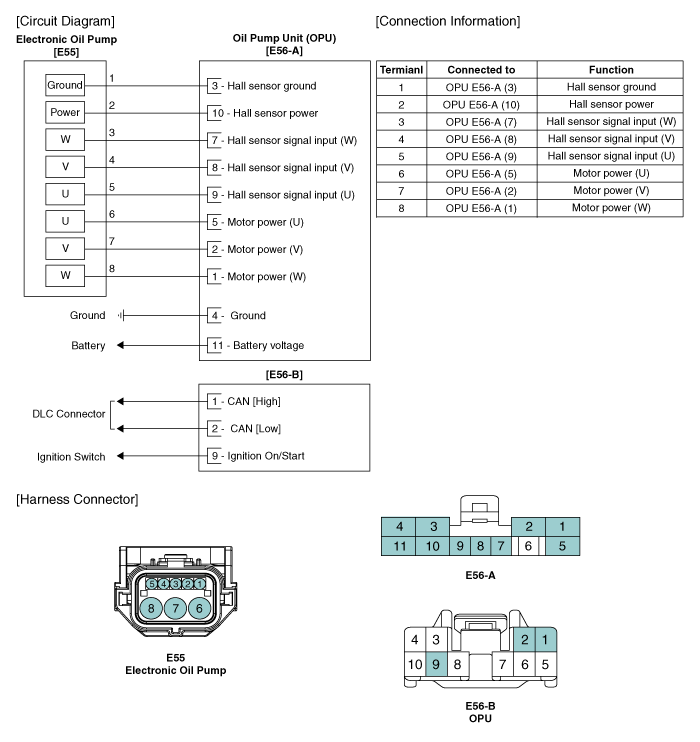
 Kia Forte: Oil Pump Unit (OPU) Circuit diagram
Second generation YD (2014-2018) / Kia Forte TD 2014-2018 Service Manual / Engine Control / Fuel System / ISG (Idle Stop & Go) System / Oil Pump Unit (OPU) Circuit diagram

 Oil Pump Unit (OPU) Connector
Opu Connector Terminal Function
E56-A
E56-B
Pin No.
Description
Pin No.
Description
1
Motor power(W)
1
...
 Oil Pump Unit (OPU) Removal
1.
Remove the negative (-) battery terminal.
2.
Remove the crash pad lower panel.
(Refer to Body - ŌĆ£Crash PadŌĆØ)
...
See also:
Intake Air Temperature Sensor (IATS) Inspection
1.
Turn the ignition switch OFF.
2.
Disconnect the IATS connector.
3.
Measure resistance between the IATS termi ...
Camshaft Position Sensor (CMPS) Description
Camshaft Position Sensor (CMPS) is a hall sensor and detects the camshaft
position by using a hall element.
It is related with Crankshaft Position Sensor (CKPS) and detects the piston
pos ...
A/C Pressure Transducer Description
The A/C Pressure Transducer (APT) converts the pressure value of high
pressure line into voltage value after measuring it. By converted voltage value,
engine ECU controls the cooling fan by o ...
Copyright ® www.kifomanual.com 2014-2025
