 Kia Forte: Instrument Cluster Circuit Diagram
Second generation YD (2014-2018) / Kia Forte TD 2014-2018 Service Manual / Body Electrical System / Indicators And Gauges / Instrument Cluster Circuit Diagram
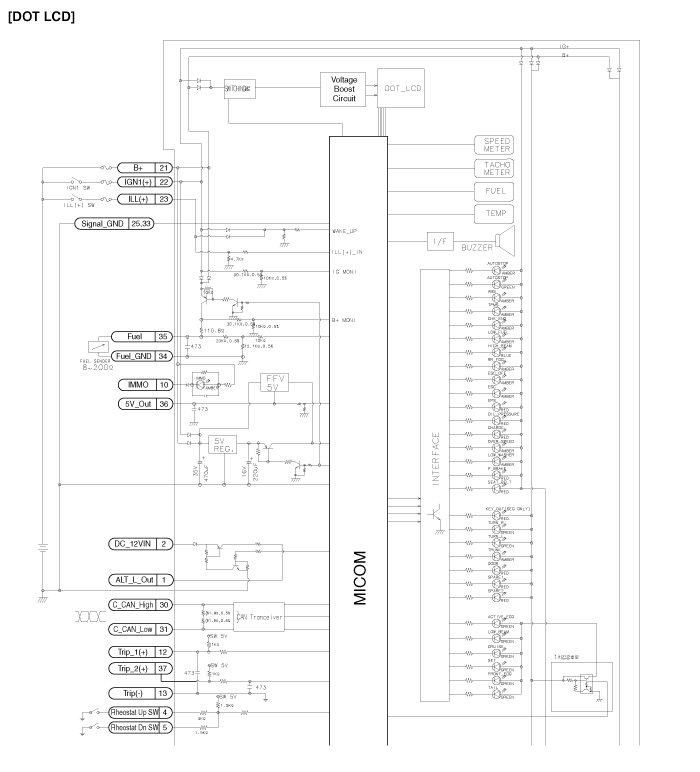
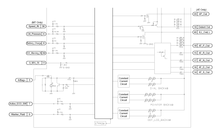
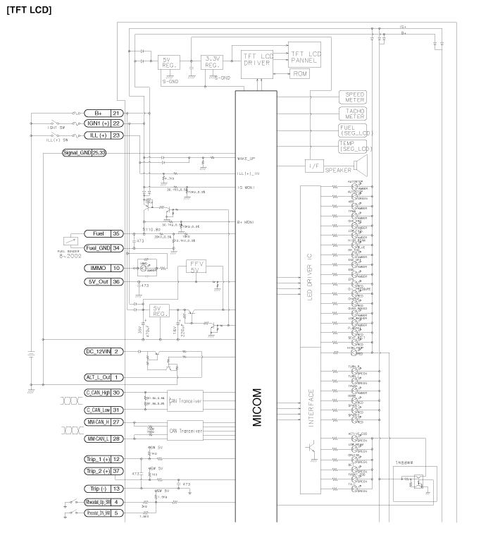
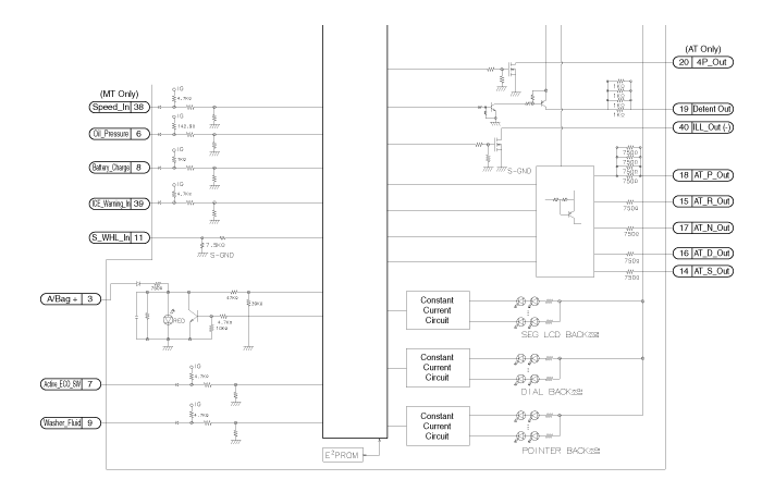
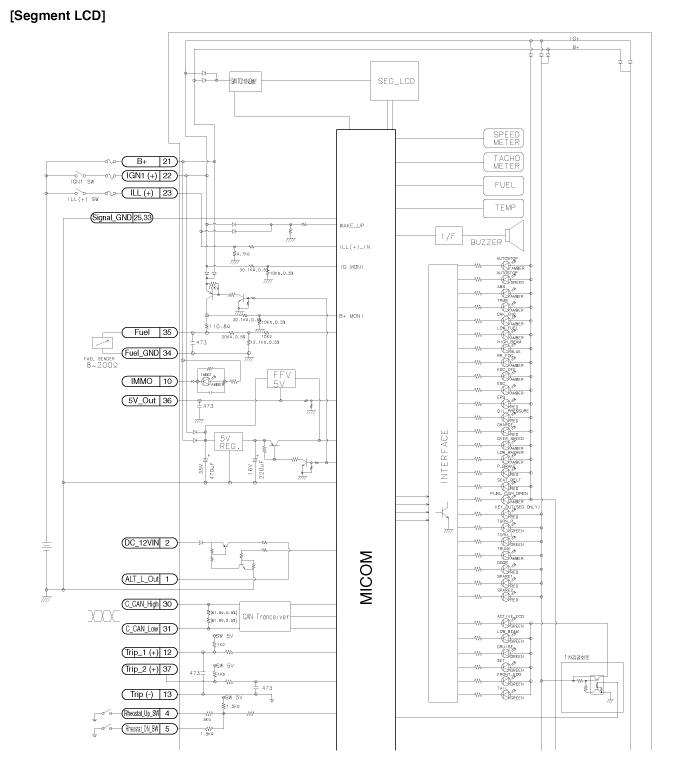
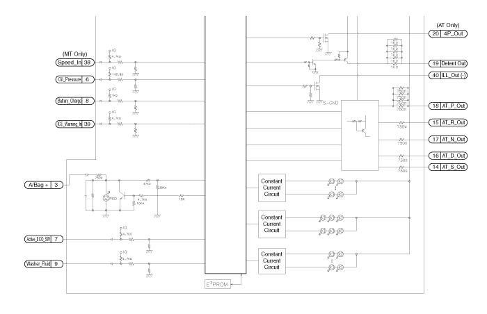
 Instrument Cluster Description
Cluster Variant Coding
As we have more options (ESC, TPMS, etc.) in the car, the dashboard now
have more information to display depending on the chosen options.
For this reason, we need ...
 Instrument Cluster Removal
1.
Disconnect the negative (-) battery terminal.
2.
Remove the cluster fascia panel.
(Refer to Body - "Cluster Fascia Panel") ...
See also:
Oil Pan Installation
1.
Install the oil screen (A) with a new gasket (B).
Tightening torque
Bolt :
19.6 ~ 26.5 N.m (2.0 ~ 2.7 kgf.m, 14.5 ~ 19.5 lb ...
Rear Wheel Guard Replacement
•
Put on gloves to protect your hands.
&nb ...
Vacuum Pump
Components
1. Vacuum pump
2. Bracket
3. Lead wire assembly
...
Copyright © www.kifomanual.com 2014-2025
