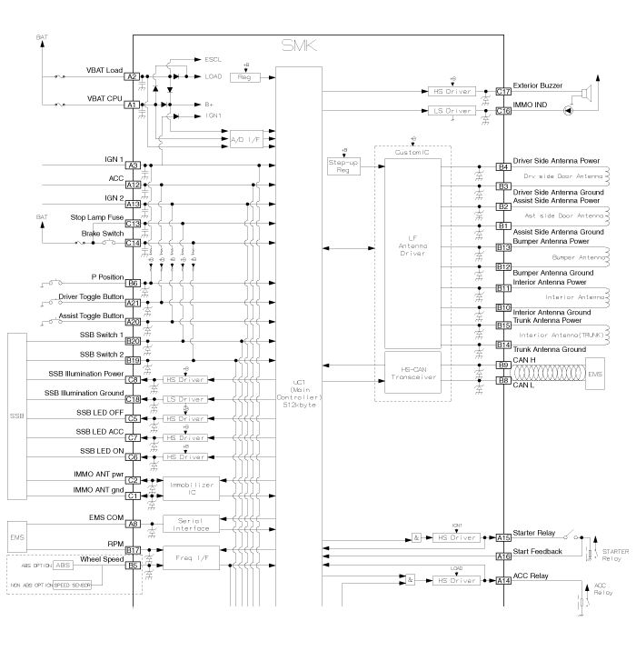
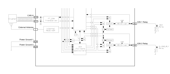
 Kia Forte: Smart Key Unit Circuit Diagram
Second generation YD (2014-2018) / Kia Forte TD 2014-2018 Service Manual / Body Electrical System / Smart Key System / Smart Key Unit Circuit Diagram


 Smart Key Unit Component
Component (1)
Connector Pin Information
No.
Connector A (24 pins)
No.
Connector B (20 pins)
No.
Connector C (18 pins)
1
VBAT CPU
...
 Smart Key Unit Inspection
Smart Key Unit
-
Refer to Smart key System - "Smart key Diagnostic"
Smart Key Switch
-
Refer to Smart key System - "Smart key D ...
See also:
DC/DC Converter Circuit Diagram
In the ISG mode, if the power of an audio system turnsOFF by drawdown
while “Auto Starting” or “Idle Starting”functi ...
Components
1. Front door inside handle cap
2. Front door pull handle cap
3. Front door trim
4. Front door panel
5. Front door side impact pad
6. Front door quadrant inner cover
7 ...
Owner maintenance
The following lists are vehicle checks and inspections that should be performed
by the owner or an authorized Kia dealer at the frequencies indicated to help ensure
safe, dependable operation of you ...
Copyright © www.kifomanual.com 2014-2025
