 Kia Forte: Components Location
Second generation YD (2014-2018) / Kia Forte TD 2014-2018 Service Manual / Engine Control / Fuel System / Engine Control System / Components Location
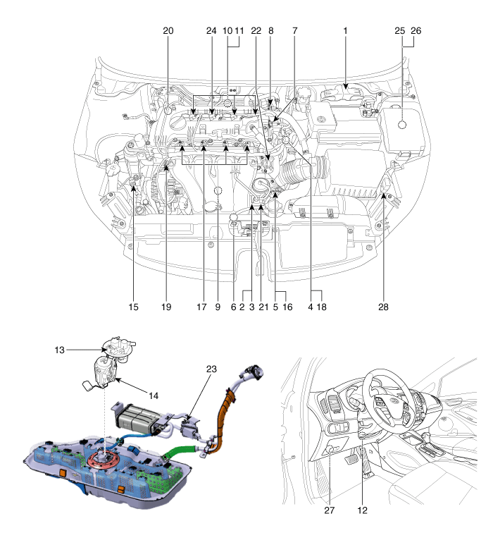
| 1. Engine Control Module (ECM) 2. Manifold Absolute Pressure Sensor (MAPS) 3. Intake Air Temperature Sensor (IATS) 4. Engine Coolant Temperature Sensor (ECTS) 5. Throttle Position Sensor (TPS) [integrated into ETC Module] 6. Crankshaft Position Sensor (CKPS) 7. Camshaft Position Sensor (CMPS) [Bank 1 / Intake] 8. Camshaft Position Sensor (CMPS) [Bank 1 / Exhaust] 9. Knock Sensor (KS) 10. Heated Oxygen Sensor (HO2S) [Bank 1 / Sensor 1] 11. Heated Oxygen Sensor (HO2S) [Bank 1 / Sensor 2] 12. Accelerator Position Sensor (APS) 13. Fuel Tank Pressure Sensor (FTPS) 14. Fuel Level Sender (FLS) |
15. A/C Pressure Transducer (APT) 16. ETC Motor [integrated into ETC Module] 17. Injector 18. Purge Control Solenoid Valve (PCSV) 19. CVVT Oil Control Valve (OCV) [Bank 1 / Intake] 20. CVVT Oil Control Valve (OCV) [Bank 1 / Exhaust] 21. Variable Intake Solenoid (VIS) Valve 22. Variable Charge Motion Actuator (VCMA) 23. Canister Close Valve (CCV) 24. Ignition Coil 25. Main Relay 26. Fuel Pump Relay 27. Data Link Connector (DLC) [16-Pin] 28. Multi-Purpose Check Connector [20-Pin] |
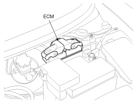
| 1. Engine Control Module (ECM) |
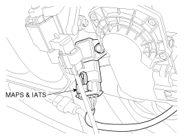
2. Manifold Absolute Pressure Sensor (MAPS) 3. Intake Air Temperature Sensor (IATS) |
|
|
|
| 4. Engine Coolant Temperature Sensor (ECTS) |
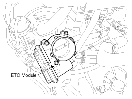
5. Throttle Position Sensor (TPS) 16. ETC Motor |
|
|
|
| 6. Crankshaft Position Sensor (CKPS) |
7. Camshaft Position Sensor (CMPS) [Bank 1 / Intake] 8. Camshaft Position Sensor (CMPS) [Bank 1 / Exhaust] |
|
|
|
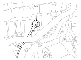
| 9. Knock Sensor (KS) |
10. Heated Oxygen Sensor (HO2S) [SULEV] 11. Heated Oxygen Sensor (HO2S) [SULEV] |
|
|
|
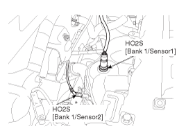
| 10. Heated Oxygen Sensor (HO2S) [Bank 1/Sensor 1] [LEV2] |
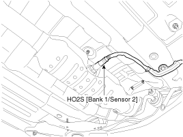
11. Heated Oxygen Sensor (HO2S) [Bank 1/Sensor 2] [LEV2] |
|
|
|
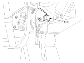
| 12. Accelerator Position Sensor (APS) |
13. Fuel Tank Pressure Sensor (FTPS) |
|
|
|
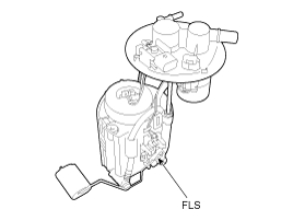
| 14. Fuel Level Sensor (FLS) |
15. A/C Pressure Transducer (APT) |
|
|
|
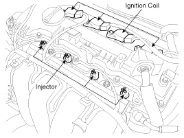
| 17. Injector 24. Ignition Coil |
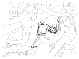
18. Purge Control Solenoid Valve (PCSV) |
|
|
|
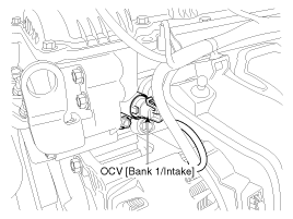
| 19. CVVT Oil Control Valve (OCV) [Bank 1 / Intake] |
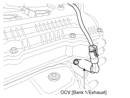
20. CVVT Oil Control Valve (OCV) [Bank 1 / Exhaust] |
|
|
|
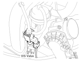
| 21. Variable Intake Solenoid (VIS) Valve |
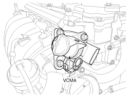
22. Variable Charge Motion Actuator (VCMA) |
|
|
|
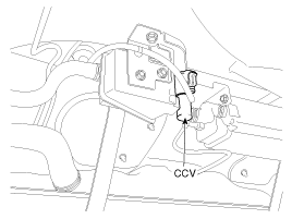
| 23. Canister Close Valve (CCV) |
25. Main Relay 26. Fuel Pump Relay |
|
|
|
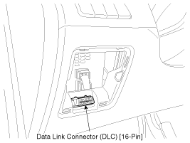
| 27. Data Link Connector (DLC) [16-Pin] |
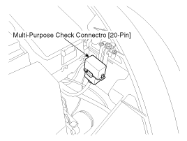
28. Multi-Purpose Check Connector [20-Pin] |
|
|
|


 OBD-II review
1. Overview
The California Air Resources Board (CARB) began regulation of On Board
Diagnostics (OBD) for vehicles sold in California beginning with the 1988 model
year. The first phase, O ...
 ECM Terminal And Input/Output signal (M/T)
ECM Terminal Function
Connector [CNG-MA]
Pin No.
Description
Connected to
1
Ignition Coil (Cylinder #1) control output
Ignition Co ...
See also:
Engine And Transaxle Assembly Removal
ŌĆó
Use fender covers to avoid damaging painted surfaces.
Ō ...
Exhaust Manifold Removal and Installation
1.
Remove the engine cover.
2.
Disconnect the battery negative terminal.
3.
Disconnect the front and rear oxyge ...
Components
Components (1)
(4Door)
1. Front bumper cover
2. Front bumper upper weatherstrip
3. Front bumper side bracket [LH]
4. Front bumper side bracket [RH]
Co ...
Categories
- Home
- Kia Forte BD 2019-2026 Owners Manual
- Kia Forte BD 2019-2026 Service Manual
- First Generation
- Second generation
- Kia Forte TD 2014-2018 Owners Manual
- Kia Forte TD 2014-2018 Service Manual

Copyright ® www.kifomanual.com 2014-2026