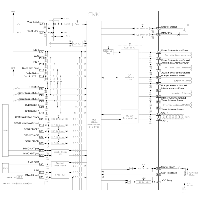
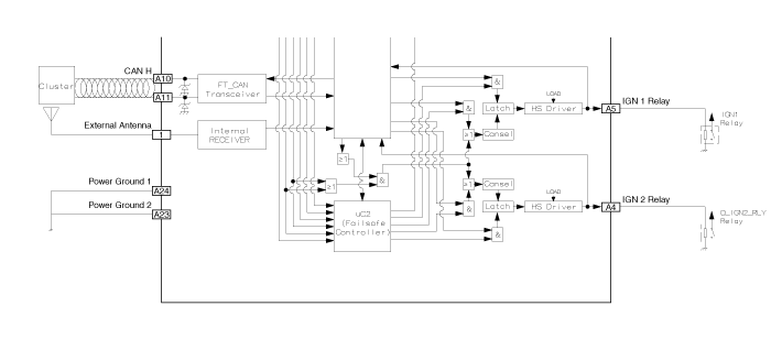
 Kia Forte: Smart Key Unit Circuit Diagram
Second generation YD (2014-2018) / Kia Forte TD 2014-2018 Service Manual / Body Electrical System / Smart Key System / Smart Key Unit Circuit Diagram


 Smart Key Unit Component
Component (1)
Connector Pin Information
No.
Connector A (24 pins)
No.
Connector B (20 pins)
No.
Connector C (18 pins)
1
VBAT CPU
...
 Smart Key Unit Inspection
Smart Key Unit
-
Refer to Smart key System - "Smart key Diagnostic"
Smart Key Switch
-
Refer to Smart key System - "Smart key D ...
See also:
Yaw-rate and Lateral G Sensor
When the vehicle is turning with respect to a vertical axis the yaw rate
sensor detects the yaw rate electronically by the vibration change of plate
fork inside the yaw rate sensor.
If ya ...
Component Location
1. EMS box assembly
(Engine control relay, Fuel pump relay,
Air conditioner compressor relay)
2. C/Fan 1 relay
3. C/Fan 2 relay
4. SSB 4(IG2) relay
5. Blower relay
...
Removal
1.
Remove the air cleaner assembly.
(Refer to Engine Mechanical System - "Air Cleaner")
2.
Remove the battery and battery tray ...
Copyright © www.kifomanual.com 2014-2024
