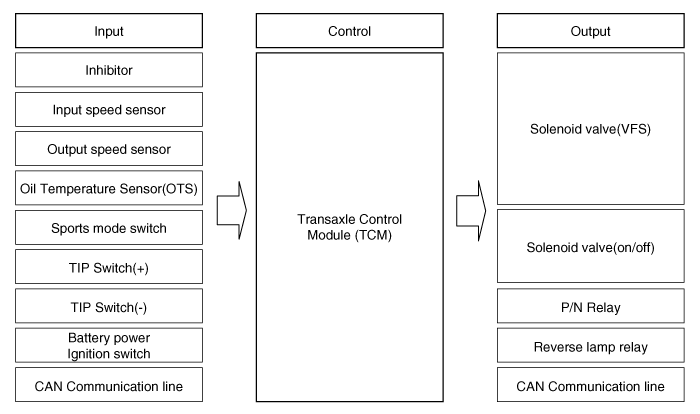
 Kia Forte: Circuit Diagram
 Adjustment
Transaxle Control Module(TCM) Learning
When shift shock is occurred or parts related with the transaxle are replaced,
TCM learning should be performed.
In the following case, TC ...
 Components Location
1. Automatic transaxle
2. Inhibitor switch
3. Transaxle Control Module (TCM)
4. Valve body cover
5. Solenoid valve connect
6. Oil temperature sensor
7. Valve body assembly ...
See also:
Instrument Cluster Control
Adjusting Instrument Cluster Illumination
The instrument panel illumination intensity can be adjusted by pressing the control
switch with the headlight switch in any position when the ignition s ...
Mode Control Actuator Description
The mode control actuator is located at the heater unit.
It adjusts the position of the mode door by operating the mode control
actuator based on the signal of the A/C control unit. Pressing ...
Operation
1.
Vehicle moving.
2.
The transmission lever position is D-range. The brake pedal is
released.
3.
The ...
Copyright © www.kifomanual.com 2014-2024