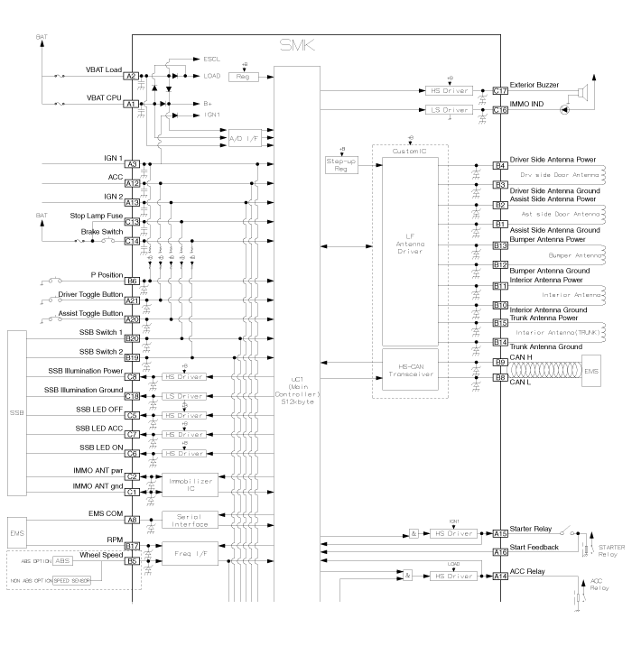
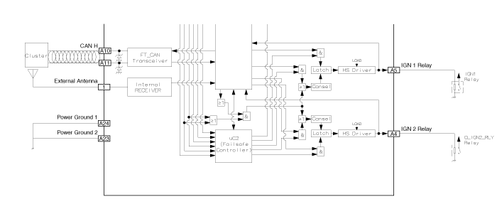
 Kia Forte: Smart Key Unit Circuit Diagram
Second generation YD (2014-2018) / Kia Forte TD 2014-2018 Service Manual / Body Electrical System / Smart Key System / Smart Key Unit Circuit Diagram


 Smart Key Unit Component
Component (1)
Connector Pin Information
No.
Connector A (24 pins)
No.
Connector B (20 pins)
No.
Connector C (18 pins)
1
VBAT CPU
...
 Smart Key Unit Inspection
Smart Key Unit
-
Refer to Smart key System - "Smart key Diagnostic"
Smart Key Switch
-
Refer to Smart key System - "Smart key D ...
See also:
Components
1. ESC Control Module (HECU)
2. Front Wheel Speed Sensor
3. Rear Wheel Speed Sensor
4. Yaw-late & Lateral G Sensor
5. Steering Wheel Angle Sensor
6. ABS Warning Lamp
...
Battery Removal
1.
Disconnect the battery terminals (A).
(1)
2.
Remove the air duct and air cleaner assembly.
...
Air Cleaner Components
1. Air intake hose
2. Air cleaner cover
3. Air cleaner filter
4. Air cleaner body
5. Resonator
6. Air duct
7. Air intake shield
...
Copyright © www.kifomanual.com 2014-2024
