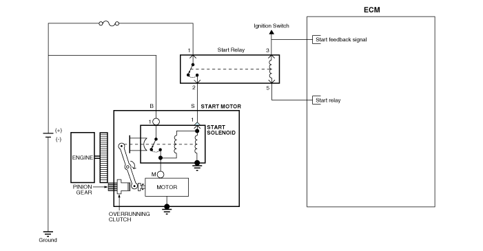
 Kia Forte: Starter Circuit Diagram
Second generation YD (2014-2018) / Kia Forte TD 2014-2018 Service Manual / Engine Electrical System / Starting System / Starter Circuit Diagram

 Starter Components
[NON-ISG Type]
1. Front bracket assembly
2. Magnet switch assembly
3. Lever
4. Reducer assembly
5. Lever stop
6. Gasket sheet
7. Yoke assembly
8. Armat ...
 Starter Removal
1.
Disconnect the battery negative terminal.
2.
Remove the air duct and air cleaner assembly.
(Refer to Engine Mechanical System - &quo ...
See also:
Front Strut Assembly Components
1. Strut assembly
2. Insulator
3. Strut bearing
4. Spring upper pad
5. Coil spring
6. Dust cover
7. Spring lower pad
...
Overdrive Clutch Control Solenoid Valve(OD/C_VFS) Description
Overdrive Clutch(OD/C) Control Solenoid Valve is attached to the valve
body. This variable force solenoid valve directly controls the hydraulic pressure
inside the Overdrive Clutch(OD/C)
...
Inhibitor Switch Description
Inhibitor Switch monitors the lever's position(P, R, N, D) and is used
to control gear setting signals.
...
Copyright © www.kifomanual.com 2014-2024
