 Kia Forte: Cooling Fan Removal and Installation
Second generation YD (2014-2018) / Kia Forte TD 2014-2018 Service Manual / Engine Mechanical System / Cooling System / Cooling Fan Removal and Installation
Cooling fan assembly
| 1. |
Disconnect the battery "-" terminal.
|
| 2. |
Remove the air duct and air cleaner assembly.
(Refer to Intake And Exhaust System - "Air Cleaner)
|
| 3. |
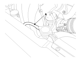
Disconnect the over flow hose (A) from the filler neck.
|
| 4. |
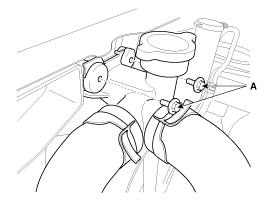
Loosen the filler neck assembly mounting bolts (A).
|
| 5. |
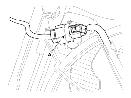
Disconnect the fan motor connector (A).
|
| 6. |
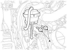
Loosen the variable Intake solenoid (VIS) actuator mounting bolts
(A).
|
| 7. |
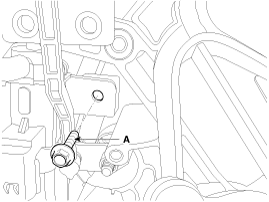
Detach the variable intake solenoid (VIS) valve & bracket after
unfastening the mounting bolt (A).
|
| 8. |
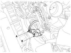
Disconnect the crankshaft position sensor (CKPS) connector (A)
and the front connector (B).
|
| 9. |
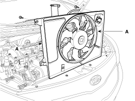
Remove the cooling fan (A).
|
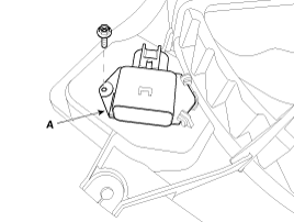
Resistor
| 1. |
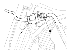
Disconnect the wire harness connector (A) and the fan motor connector
(B).
|
| 2. |
Remove the resistor (A) from the cooling fan shroud.
|
| 3. |
Install in the reverse order of removal.
|
 Cooling Fan Disassembly
1.
Remove the cooling fan (A) from the cooling fan assembly.
2.
Disconnect the fan motor connector (A) from the resistor.
...
See also:
Front Stabilizer Link Replacement
1.
Loosen the wheel nuts slightly.
Raise the vehicle, and make sure it is securely supported.
2.
Remove the front wheel and tire (A ...
Rear Torsion Beam Axle Components
1. Rear torsion beam axle
...
Troubleshooting
Problem
Possible cause
Solution
Not pairing
Bluetooth device of Car is not discoverable mode
Enter Bluetooth pairing (searching) mode
UserŌ ...
Copyright ® www.kifomanual.com 2014-2026

