 Kia Forte: CVVT & Camshaft Installation
Second generation YD (2014-2018) / Kia Forte TD 2014-2018 Service Manual / Engine Mechanical System / Cylinder Head Assembly / CVVT & Camshaft Installation
| 1. |
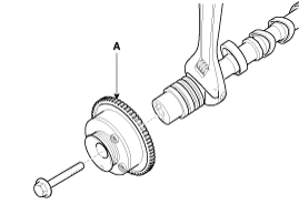
Install the CVVT assembly (A) to the camshaft.
|
| 2. |
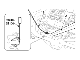
Compress the tensioner plunger using a pry bar (A) and then insert
the stopper pin (B) into the hole in the tensioner to hold the compressed
plunger.
|
| 3. |
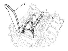
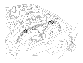
Place the intake camshaft (A) and then insert the tensioner arm
(B) along the timing chain.
|
| 4. |
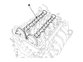
Place the exhaust camshaft (A).
|
| 5. |
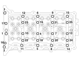
Install the camshaft bearing caps.
Tighten the bolts, in several passes, in the sequence as shown.
|
| 6. |
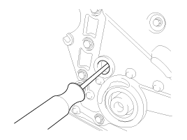
Using a suitable tool, move the tensioner arm to align the tensioner
bolt hole with the service hole.
|
| 7. |
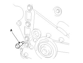
Install the tensioner arm bolt (A).
|
| 8. |
Remove the stopper pin from the tensioner.
|
| 9. |
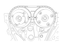
Turn the crankshaft two turns in the operating direction (clockwise),
and then check that the TDC marks of the CVVT sprockets are in straight
line on the cylinder head surface.
|
| 10. |
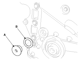
Install a service plug bolt (A) with a gasket.
|
| 11. |
Install the crankshaft damper pulley.
(Refer to Timing System - “Crankshaft Damper Pulley”)
|
| 12. |
Install the cylinder head cover.
(Refer to Cylinder Head Assembly - “Cylinder Head Cover”)
|
 CVVT & Camshaft Inspection
Camshaft
1.
Inspect the cam lobes.
Using a micrometer, measure the cam lobe height.
If the cam lobe height is less than specification, replace the
camsh ...
 Cylinder Head Components
1. Camshaft bearing cap
2. Camshaft front bearing cap
3. Exhaust camshaft
4. Intake camshaft
5. Exhaust CVVT assembly
6. Intake CVVT assembly
7. Cam carrier
8. Cyli ...
See also:
Replacement
Front brake pads
1.
Loosen the guide rod bolt (B) and pivot the caliper (A) up out
of the way.
Tightening torque:
21.6 ~ 31.4 N.m ...
Multimedia Jack Description
The multimedia jack on the console upper cover is for customers who like
to listen to external portable music players like the MP3, iPod and etc., through
the vehicle's sound system when ...
Injector Description
Based on information from various sensors, the ECM can calculate the fuel
amount to be injected. The fuel injector is a solenoid-operated valve and the
fuel injection amount is controlled by ...
Copyright © www.kifomanual.com 2014-2025

