 Kia Forte: Inspection
Test the horn by connecting battery voltage to the 1 terminal and ground
the 2 terminal.
The horn should make a sound. If the horn fails to make a sound, replace
it.
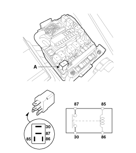
Horn Relay Inspection
| 1. |
Remove the horn relay (A) from the engine room relay box.
|
| 2. |
There should be continuity between the No.30 and No.87 terminals
when power and ground are connected to the No.85 and No.86 terminals.
|
| 3. |
There should be no continuity between the No.30 and No.87 terminals
when power is disconnected.
|
 Component Location
1. Horn switch
2. Horn relay (Engine room compartment)
3. Clock spring
4. Horn
...
 Removal
1.
Disconnect the negative (-) battery terminal.
2.
Remove the front bumper cover.
(Refer to Body - "Front Bumper Cover")
...
See also:
Front Disc Brake
Components
1. Guide rod bolt
2. Bleed screw
3. Caliper carrier
4. Caliper body
5. Inner pad shim
6. Brake pad
7. Pad retainer
...
Inhibitor Switch Description
Inhibitor Switch monitors the lever's position(P, R, N, D) and is used
to control gear setting signals.
...
Engine compartment
1. Engine oil filler cap
2. Engine oil dipstick
3. Brake/clutch fluid reservoir
4. Air cleaner
5. Fuse box
6. Positive battery terminal
7. Negative battery terminal
8. Windshiel ...
Copyright © www.kifomanual.com 2014-2025


