 Kia Forte: Description
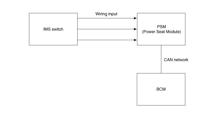
| System Outline |
An optimal seat position set by a driver can be memorized in Power seat
unit by IMS SW, which enables restoration of seat position set by the driver
despite.
Playing of this function during drive is banned for safety reasons, and
it has emergency stop function of restoration and gearing operation as well.

Input Specification
| 1. |
IGN2
IGN switch input is determined by Local switch УIGN2Ф.
|
| 2. |
SEAT MANUAL switch : SEAT Input
|
| 3. |
SEAT position Sensor (pulse Signal)
Sensing movement amount of Slide, Recline, Front rear height,
and Rear right height motor
|
| 4. |
Dr Door switch
Sensing that drive door opens
|
| 5. |
Speed
This signal is received for sensing vehicle speed by BCM
|
| 6. |
IMS switch
|
| 7. |
CAN Communication LINE
|
Transmitting communication signals between IMS and BCM
CHATTERING Control in Input Signal
| 1. |
Input switch - 40ms delay
SLIDE, RECLINE, Front rear height, rear right HEIGHT switch
УPФ Position switch, SPEED, KEY IN, LOCAL KEY IN switch, DR DOOR
switch, IGN2 switch
|
| 2. |
IGN switch input is determined by Local switch УIGN2.
|
TIME Error
| 1. |
±10%, for TIME without error indication
±50ms, for TIME not exceeding 500ms
|
| 2. |
Indicated time in each function does not include Time of controlling
CHATTERING started from changing point of rr input.
|
 Component Location
1. Seat Memory Unit (IMS)
2. IMS control switch
3. IMS driver power seat control
...
 Operation
Control Specification
1.
MANUAL Operation
(1)
MANUAL Seat Operation SEAT is to be operated by MANUAL
switch Input of SEAT. SLI ...
See also:
Rear Door Belt Outside Weatherstrip Replacement
(4Door, 5Door)
1.
Pull down rear door window glass by pressing the power window
glass switch.
2.
After loosening the mounting ...
Installation
1.
Install in the reverse order of removal.
2.
Adjust the ignition lock switch.
(1)
In state of full stro ...
Telemetics Unit (TMU) Inspection
1.
After replacing the TMU unit, access Dealer Engineering Mode in
head unit.
(Refer to MTS system - "TMU Dealer Engineering Mode")
2 ...
Copyright © www.kifomanual.com 2014-2025
