 Kia Forte: IMS Control Switch Inspection
Second generation YD (2014-2018) / Kia Forte TD 2014-2018 Service Manual / Body Electrical System / IMS (Integrated Memory) / IMS Control Switch Inspection
| 1. |
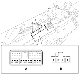
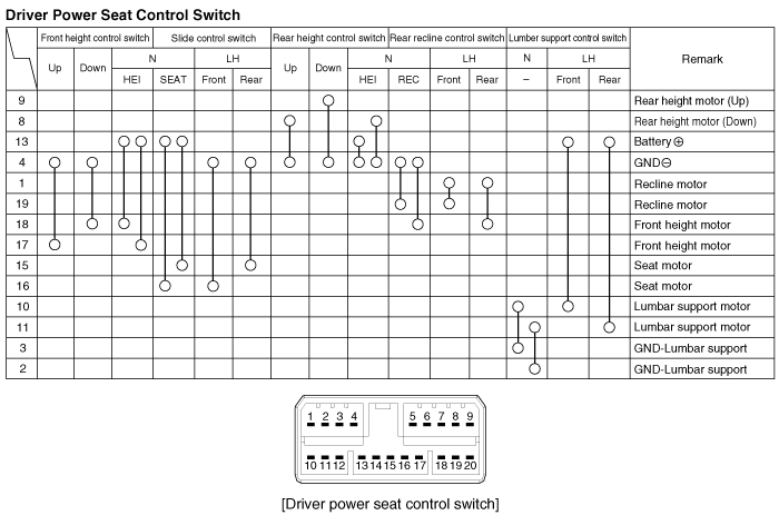
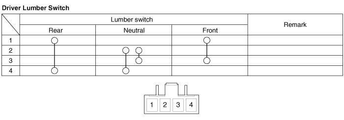
With the power seat switch in each position, make sure that continuity
exists between the terminals below. If continuity is not as specified,
replace the power seat switch.
A : Power seat control switch
B : Lumbar support switch
|
 IMS Control Switch Removal
1.
Disconnect the negative (-) battery terminal.
2.
Remove the seat side cover (A).
3.
Disconnect the p ...
See also:
Shift Lever Components
1. Shift lever knob
2. Shift lever assembly
3. Shift cable assembly
4. Select cable assembly
5. Retainer
...
Transaxle Oil Temperature Sensor Circuit Diagram
...
AVN Head Unit Removal
AVN Head Unit
•
Take care not to scratch the center fascia panel and related
parts.
...
Copyright © www.kifomanual.com 2014-2025


