
 Kia Forte: Thermostat Removal and Installation
Second generation YD (2014-2018) / Kia Forte TD 2014-2018 Service Manual / Engine Mechanical System / Cooling System / Thermostat Removal and Installation
Disassembly of the thermostat would have an adverse effect, causing
a lowering of cooling efficiency. Do not remove the thermostat, even
if the engine tends to overheat.
|

| 1. |
Drain engine coolant so its level is below thermostat.
|
| 2. |
Disconnect the radiator lower hose.
(Refer to Cooling System - “Radiator Hose”)
|
| 3. |
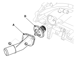
Remove the water inlet fitting (A) and thermostat (B).
|
| 4. |
Remove the intake manifold.
(Refer to Intake and Exhaust System - "Intake Manifold")
|
| 5. |
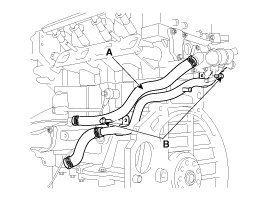
Remove the bypass hose (A).
|
| 6. |
Unfasten the heater pipe mounting bolts (B) and then remove the
heater pipe.
|
| 7. |
Install in the reverse order of removal.
|
| 8. |
Fill the engine coolant.
|
| 9. |
Start the engine and check for leaks.
|
| 10. |
Recheck the coolant level.
|
 Thermostat Components
1. Water inlet fitting
2. Thermostat
3. Bypass hose
4. Heater pipe & hose assembly
...
 Thermostat Inspection
1.
Immerse the thermostat in water and gradually heat the water.
2.
Check the valve opening temperature.
If the valve opening te ...
See also:
Control Shaft Complete Description
Component location : Control shaft
assembly is mounted on the top of the manual transaxle
Function : Change the gear by shifting
a shift lever. ...
Instrument Cluster Components
Connector Pin Information
No.
Description
No.
Description
1
Alternator L output
21
Battery (+)
2
I ...
Purge Control Solenoid Valve (PCSV) Installation
•
Install the component with the specified torques.
•
...
Categories
- Home
- Kia Forte BD 2019-2026 Owners Manual
- Kia Forte BD 2019-2026 Service Manual
- First Generation
- Second generation
- Kia Forte TD 2014-2018 Owners Manual
- Kia Forte TD 2014-2018 Service Manual

Copyright � www.kifomanual.com 2014-2026