 Kia Forte: Exhaust Manifold Removal and Installation
Second generation YD (2014-2018) / Kia Forte TD 2014-2018 Service Manual / Engine Mechanical System / Intake And Exhaust System / Exhaust Manifold Removal and Installation
| 1. |
Remove the engine cover.
|
| 2. |
Disconnect the battery negative terminal.
|
| 3. |
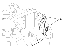
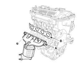
Disconnect the front and rear oxygen sensor connectors (A) and
then remove them from the bracket.
|
| 4. |
Remove the front muffler.
(Refer to Intake And Exhaust System - "Muffler")
|
| 5. |
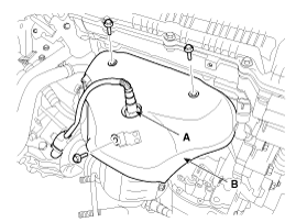
Remove the front oxygen sensror (A).
(Refer to Engine Control/Fuel System - "Heated Oxygen Sensor (HO2S)")
|
| 6. |
Remove the exhaust manifold heat protector (B).
|
| 7. |
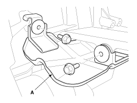
Remove the driveshaft heat protector (A).
|
| 8. |
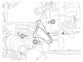
Remove the exhaust manifold stay (A).
|
| 9. |
Remove the exhaust manifold (A) with the gasket (B).
|
| 10. |
Install in the reverse order of removal.
|
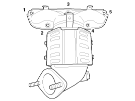
 Exhaust Manifold Components
1. Heat protector
2. Exhaust manifold gasket
3. Exhaust manifold
4. Exhaust manifold stay
...
 Muffler Components
1. Front muffler
2. Catalytic converter & center muffler assembly
3. Main muffler
4. Gasket
5. Hanger
...
See also:
System Block Diagram
Component Parts And Function Outline
Component part
Function
Vehicle-speed sensor
Converts vehicle speed to pulse.
ECM
Receives signals fr ...
Special Service Tools
Tool Name / Number
Illustration
Description
09411-1P000
Clutch disc guide
Used for holding clutch disc when installing
...
Specification
Tightening Torques
Item
N.m
kgf.m
lb-ft
Passenger Airbag (PAB)
8.0 ~ 9.0
0.82 ~ 0.92
5.9 ~ 6.7
Curtain Airbag (CAB)
...
Copyright © www.kifomanual.com 2014-2025

