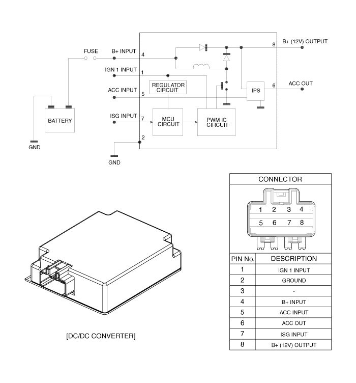
 Kia Forte: DC/DC Converter Circuit Diagram
Second generation YD (2014-2018) / Kia Forte TD 2014-2018 Service Manual / Engine Control / Fuel System / ISG (Idle Stop & Go) System / DC/DC Converter Circuit Diagram
In the ISG mode, if the power of an audio system turnsOFF by drawdown
while ŌĆ£Auto StartingŌĆØ or ŌĆ£Idle StartingŌĆØfunction operates, replace the
DC/DC converter.
|

 DC/DC Converter Component Location
1. DC/DC Converter [200W]
...
 DC/DC Converter Removal
1.
Disconnect the battery negative (-) cable.
2.
Remove the crash pad lower panel.
(Refer to Body - Crash pad lower panel.)
...
See also:
Climate control system
čö
1. Fan speed control knob
2. Mode selection knob
3. Temperature control knob
4. Air conditioning button
5. Air intake control button
6. Rear window defroster button
Heating and air conditi ...
Telemetics Unit (TMU) Installation
1.
Install the MTS unit after connecting the cable and connector.
2.
Install the glove box housing.
3.
Connect ...
Immobilizer Control Unit Installation
1.
Install the immobilizer unit.
2.
Connector the immobilizer unit.
3.
Install the crash pad lower panel.
...
Categories
- Home
- Kia Forte BD 2019-2026 Owners Manual
- Kia Forte BD 2019-2026 Service Manual
- First Generation
- Second generation
- Kia Forte TD 2014-2018 Owners Manual
- Kia Forte TD 2014-2018 Service Manual

Copyright ® www.kifomanual.com 2014-2026