 Kia Forte: Fuel Pump Inspection
Second generation YD (2014-2018) / Kia Forte TD 2014-2018 Service Manual / Engine Control / Fuel System / Fuel Delivery System / Fuel Pump Inspection
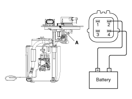
[Fuel pump]
| 1. |
Turn ignition switch OFF and disconnect the negative (-)battery
cable.
|
| 2. |
Remove the fuel pump assembly.
|
| 3. |
Check motor operation by fuel pump connector (A) connecting power(No.2)
and ground(No.4)
|
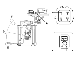
[Fuel sender]
| 1. |
Turn ignition switch OFF and disconnect the negative (-)battery
cable.
|
| 2. |
Remove the fuel pump assembly.
|
| 3. |
Using an ohmmeter, measure the resistance between terminals 1
and 3 of sender connector (A) at each float level.
|
| 4. |
Also check that the resistance changes smoothly when the float
is moved from "E" to "F".
|
 Fuel Tank Installation
1.
Install in the reverse order of removal.
Fuel tank band installation
nut:
39.2 ~ 54.0 N.m (4.0 ~ 5.5 kgf.m, 28.9 ~ 39.8 lb-ft)
...
 Fuel Pump Removal
[LEV2]
1.
Release the residual pressure in fuel line (Refer to the Fuel
Delivery System - Repair Procedures - "Release Residual Pressure in
Fuel Line ...
See also:
Power Window Switch Circuit Diagram
Driver Power Window Switch
[Driver/Passenger Safety]
[Driver Auto Down]
Passenger Power Window Switch
Rear Power Window Switch
...
Trunk Lid Latch Component Location
(4Door)
1. Trunk lid latch assembly
(2Door)
1. Trunk lid latch assembly
...
Description
Automatic transaxle system relies on various measurement data to determine
the current control status and extrapolate the necessary compensation values.
These values are used to control the a ...
Copyright ® www.kifomanual.com 2014-2025


