 Kia Forte: Inhibitor Switch Installation
Second generation YD (2014-2018) / Kia Forte TD 2014-2018 Service Manual / Automatic Transaxle System / Automatic Transaxle Control System / Inhibitor Switch Installation
| 1. |
Check that the shift lever is placed in the "N" position
|
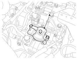
| 2. |
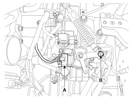
Install the inhibitor switch (A).
|
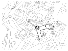
| 3. |
Install the manual control lever (A).
|
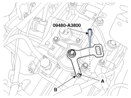
| 4. |
Align the hole (A) in the manual control lever with the "N" position
hole (B) of the inhibitor switch and then insert the SST inhibitor switch
guide pin (09480-A3800).
|
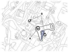
| 5. |
Tighten the nut (A) and bolts (B) with the specified torque.
|
| 6. |
Remove the SST (09480-A3800) from the hole.
|
| 7. |
Connect the inhibitor switch connector (A).
|
| 8. |
Install the shift cable by tightening nut (B).
|
| 9. |
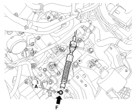
Push the shift cable to the arrow "F" to eliminate free play and
then tighten the nut (A) with the specified torque.
|
| 10. |
Install the battery and battery tray.
(Refer to Engine Electrical System - "Battery")
|
| 11. |
Install the air cleaner assembly.
(Refer to Engine Mechanical System - "Air cleaner")
|
 Inhibitor Switch Removal
1.
Place the shift lever into the "N" position.
2.
Remove the air cleaner.
(Refer to Engine Mechanical System - "Air clea ...
 Shift Lever Components
1. Shift lever knob
2. Shift lever assembly
3. Shift cable assembly
4. Shift lever knob & boots assembly
5. Manual control lever
6. Retainer
...
See also:
IMS Power Seat Control Removal
1.
Disconnect the negative (-) battery terminal.
2.
Remove the front door trim.
(Refer to Body - "Front Door Trim")
...
Starter Description
The starting system includes the battery, starter, solenoid switch, inhibitor
switch (A/T), ignition switch, ignition lock switch, connection wires and the
battery cable.
When the ignitio ...
Side Impact Sensor (SIS)
Side Impact Sensor (SIS) system consists of two P-SIS which are installed
at each center of the front door module (LH and RH) and two SIS which are installed
at each center pillar nearby (LH ...
Copyright © www.kifomanual.com 2014-2025


