 Kia Forte: Fuel Filter Removal
Second generation YD (2014-2018) / Kia Forte TD 2014-2018 Service Manual / Engine Control / Fuel System / Fuel Delivery System / Fuel Filter Removal
| 1. |
Remove the fuel pump (Refer to ŌĆ£Fuel PumpŌĆØ in this group).
|
| 2. |
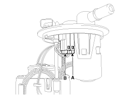
Disconnect the electric pump wiring connector (A) and the fuel
sender connector (B).
|
| 3. |
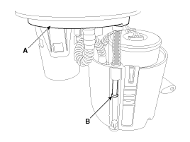
Remove the head assembly (A) after releasing the cushion fixing
clip (B).
|
| 4. |
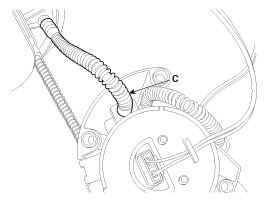
Disconnect the fuel tube quick-connectors (C).
|
| 5. |
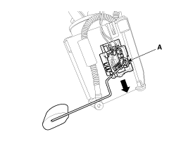
Remove the fuel sender (A) in the direction of an arrow.
|
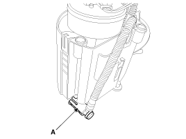
| 6. |
Disconnect the fuel tube connector (A).
|
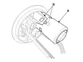
| 7. |
Remove the cut valve (A) after releasing hooks (B).
|
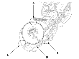
| 8. |
Remove the reservior-cup (B) after releasing the fixing hooks
(A).
|
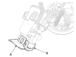
| 9. |
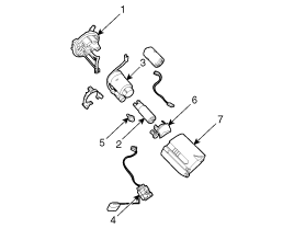
Release the fixing hooks, and then remove the pre-filter (A) and
the fuel pressure regulator (B).
1. Head Assembly
2. Electric Pump Motor
3. Fuel Filter
4. Fuel Sender
5. Fuel Pressure Regulator
6. Pre-filter
7. Reservoir cup
|
 Fuel Pump Installation
1.
Install in the reverse order of removal.
Be careful of fuel pump direc ...
 Fuel Filter Installation
1.
Install in the reverse order of removal.
...
See also:
Description
Component location : Manual transaxle
case
Operation principle : Back up lamp
switch is pushed by the reverse lug sliding when select arm, and switches the
back up lamp.
Funct ...
Tail Gate Lift Replacement
(5Door)
ŌĆó
Take care to not let the tailgate fall on you as the lifts
are ...
Alternator On-vehicle Inpection
ŌĆó
Check that the battery cables are connected to the correct
terminals.
...
Copyright ® www.kifomanual.com 2014-2026

