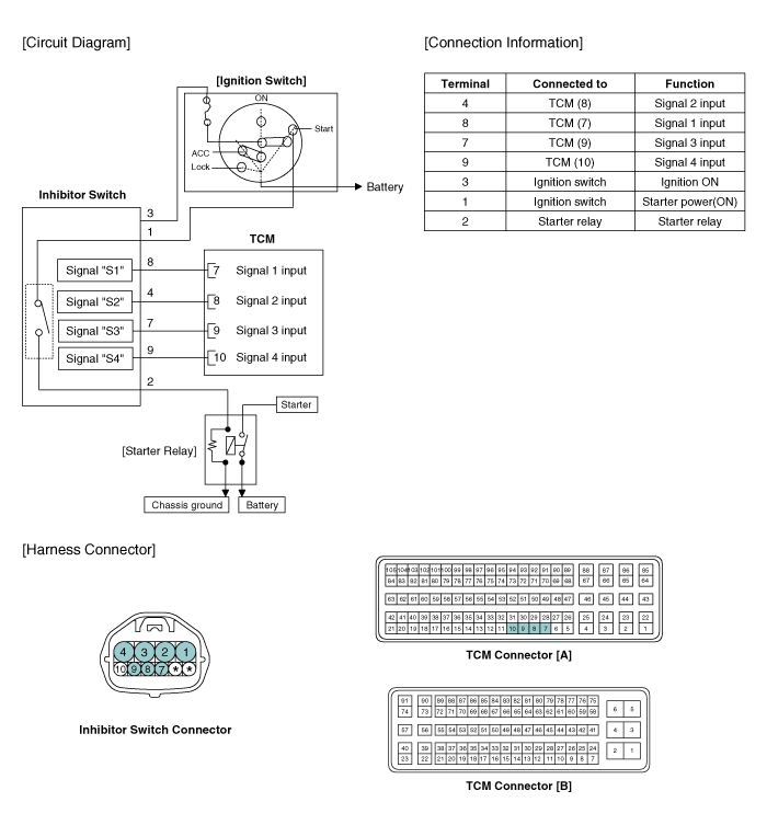
 Kia Forte: Inhibitor Switch Circuit Diagram
Second generation YD (2014-2018) / Kia Forte TD 2014-2018 Service Manual / Automatic Transaxle System / Automatic Transaxle Control System / Inhibitor Switch Circuit Diagram

 Inhibitor Switch Specifications
▷ Type: Combination of output signals from 4 terminals
Power supply (V)
12
Output type
Combination of output signals
Signal Code Table
...
 Inhibitor Switch Inspection
•
Thoroughly check connectors for looseness, poor connection,
bending, corrosion, contam ...
See also:
Rear Console Cover Component Location
1. Rear console cover
...
Manifold Absolute Pressure Sensor (MAPS) Description
Manifold Absolute Pressure Sensor (MAPS) is a speed-density type sensor
and is installed on the surge tank. It senses absolute pressure of the surge
tank and transfers the analog signal propo ...
Underdrive Brake Control Solenoid Valve(UD/B_VFS) Description
Underdrive Brake(UD/B) Control Solenoid is attached to the valve body.
This variable force solenoid valve directly controls the hydraulic pressure
inside the Underdrive Brake(UD/B).
...
Copyright © www.kifomanual.com 2014-2025
