 Kia Forte: Parking Brake Cable Installation
Second generation YD (2014-2018) / Kia Forte TD 2014-2018 Service Manual / Brake System / Parking Brake System / Parking Brake Cable Installation
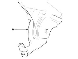
| 1. |
Install the parking brake cable (A).
|
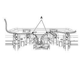
| 2. |
Install the parking brake cable (B), and then install the clip
(A).
|
| 3. |
Install the rear tire and wheel.
|
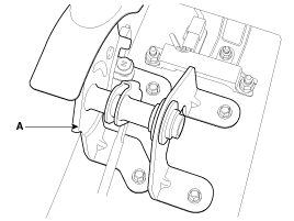
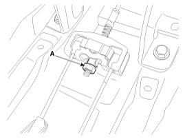
| 4. |
Install the parking brake cable (B) and then cable retainer (A).
|
| 5. |
Apply a coating of the specified grease to each sliding parts
(A) of the ratchet plate or the ratchet pawl.
|
| 6. |
Install the parking brake cable adjuster, then adjust the parking
brake lever stroke by turning adjusting nut (A).
|

| 7. |
Release the parking brake lever fully, and check that parking
brakes do not drag when the rear wheels are turned. Readjust if necessary.
|
| 8. |
Make sure that the parking brakes are fully applied when the parking
brake lever is pulled up fully.
|
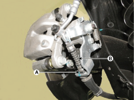
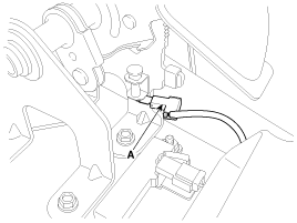
| 9. |
Reconnect the connector (A) of parking brake switch.
|
| 10. |
Install the floor console.
(Refer to Body - "Floor console")
|
 Parking Brake Cable Removal
The parking brake cables must not be bent or distorted. This will
lead to stiff operation and premature failure.
...
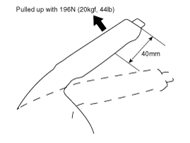
 Parking Brake Cable Adjustment
Parking Brake Lever Stroke Adjustment
1.
Remove the floor console.
(Refer to Body group - "Floor console")
2.
Apply the b ...
See also:
Installation
1.
Install in the reverse order of removal.
2.
Tighten the vacuum pump mounting bolts to the specified torque.
...
Positive Crankcase Ventilation (PCV) Valve Inspection
1.
Insert a thin stick (A) into the PCV valve (B) from the threaded
side to check that the plunger movement.
...
Description
Limitations Of The Navigation system
GPS Signal Reception State
As the GPS satellite frequency is received/transmitted in straight lines,
reception may not work if hiding devices are pla ...
Categories
- Home
- Kia Forte BD 2019-2026 Owners Manual
- Kia Forte BD 2019-2026 Service Manual
- First Generation
- Second generation
- Kia Forte TD 2014-2018 Owners Manual
- Kia Forte TD 2014-2018 Service Manual

Copyright ® www.kifomanual.com 2014-2026