 Kia Forte: Rear Torsion Beam Axle Replacement
Second generation YD (2014-2018) / Kia Forte TD 2014-2018 Service Manual / Suspension System / Rear Suspension System / Rear Torsion Beam Axle Replacement
| 1. |
Loosen the wheel nuts slightly. Raise the vehicle, and make sure
it is securely supported.
|
| 2. |
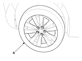
Remove the front wheel and tire (A) from front hub.
|
| 3. |
Remove the rear brake caliper.
(Refer to Brake System - "Rear Disc Brake")
|
| 4. |
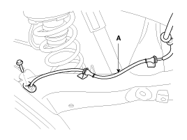
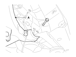
Loosen the bolt and then remove the wheel speed sensor cable (A).
|
| 5. |
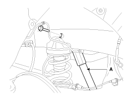
Loosen the bolt and then remove the rear shock absorber (A) from
the frame.
|
| 6. |
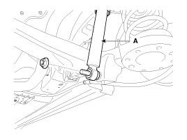
Loosen the bolt & nut and then remove the rear shock absorber
(A) from the torsion beam axle.
|
| 7. |
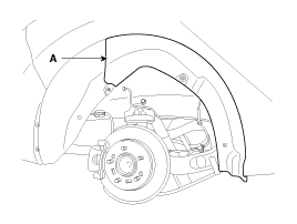
Remove the rear wheel housing (A).
|
| 8. |
Loosen the mounting bolts and then remove the torsion beam axle
(A) from the frame.
|
| 9. |
Remove the rear hub assembly.
(Refer to Driveshaft and axle - "Rear Hub - Carrier")
|
| 10. |
Installation is the reverse of removal.
|
| 11. |
Check the rear alignment.
(Refer to Rear Suspension System - "Rear Alignment")
|
 Rear Torsion Beam Axle Components
1. Rear torsion beam axle
...
 Rear Torsion Beam Axle Inspection
1.
Check the hub for cracks and the splines for wear.
2.
Check the rear axle carrier for cracks.
...
See also:
Rear Body
* These dimensions indicated in this figure are
actual-measurement dimensions. [ Unit : mm (inch) ]
Side outer p ...
Description
TREAD Lamp
-
Tire Under Inflation / Leak Warning.
1.
Turn on condition
A.
When tire pressure is below a ...
Front Cross Member
* These dimensions indicated in this figure are
actual-measurement dimensions. [ Unit : mm (inch) ]
...
Copyright ® www.kifomanual.com 2014-2025

