 Kia Forte: Smart Key Unit Removal
Second generation YD (2014-2018) / Kia Forte TD 2014-2018 Service Manual / Body Electrical System / Smart Key System / Smart Key Unit Removal
Smart Key Unit
| 1. |
Disconnect the negative (-) battery terminal.
|
| 2. |
Remove the main crash pad assembly.
(Refer to Body - "Main Crash Pad Assembly")
|
| 3. |
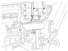
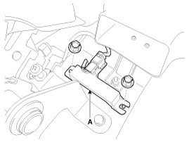
Remove the RF receiver (A) after loosening a nut.
|
| 4. |
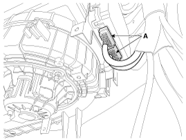
Disconnect the SMK connectors (A) from the SMK unit.
|
| 5. |
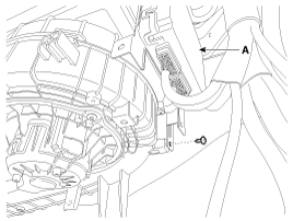
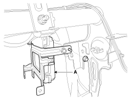
Remove the smart key unit (A) with loosening the nut and screw.
|
Interior Antenna
Take care not to scratch the crash pad and related parts.
|
| 1. |
Disconnect the negative(-) battery terminal.
|
| 2. |
Remove the floor console assembly.
(Refer to Body - "Floor Console Assembly")
|
| 3. |
Disconnect the connector, then remove the interior antenna (A)
with loosening 2 nuts.
|
Trunk Antenna
| 1. |
Disconnect the negative(-) battery terminal.
|
| 2. |
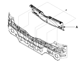
Using a clip remover, detach the clips, and remove the rear transverse
trim (A).
|
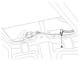
| 3. |
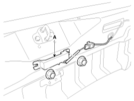
Disconnect the connector, then remove the trunk antenna (A) with
loosening 2 nuts.
|
Exterior Bumper Antenna
| 1. |
Disconnect the negative(-) battery terminal.
|
| 2. |
Remove the rear bumper cover.
(Refer to Body - "Rear Bumper Cover")
|
| 3. |
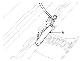
Disconnect the connector, then remove the rear bumper antenna
(A) with loosening 2 screws.
|
Buzzer
| 1. |
Disconnect the negative(-) battery terminal.
|
| 2. |
Remove the front left wheel guard.
|
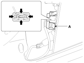
| 3. |
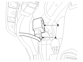
Remove the buzzer (B) after disconnecting the connector (A).
|
Door Outside Handle
| 1. |
Disconnect the negative (-) battery terminal.
|
| 2. |
Remove the front door module.
(Refer to Front Door - "Front Door Module")
|
| 3. |
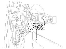
Disconnect the front door outside handle connector (A).
|
| 4. |
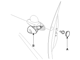
Remove the hole plug (A).
|
| 5. |
After loosening the mounting bolt, then remove the front door
outside handle cover (B).
|
| 6. |
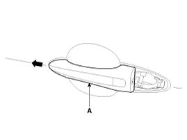
Remove the front door outside handle (A) by sliding it rearward.
|
Trunk Lid Open Switch
| 1. |
Disconnect the negative (-) battery terminal.
|
| 2. |
Remove the trunk lid trim.
(Refer to Body - "Trunk Lid Trim")
|
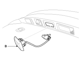
| 3. |
Disconnect the trunk lid open switch connector (A).
|
| 4. |
Remove the trunk outside handle (B) after pressing the clips (A).
|
 Smart Key Unit Inspection
Smart Key Unit
-
Refer to Smart key System - "Smart key Diagnostic"
Smart Key Switch
-
Refer to Smart key System - "Smart key D ...
 Smart Key Unit Installation
Smart Key Unit
1.
Install the smart key unit and RF receiver.
2.
Connect the connector and install the smart key unit.
...
See also:
Components
1. Driver Airbag (DAB)
2. Steering Wheel
3. Clock Spring
...
Auto Head Lamp Leveling Unit Installation
1.
Install the head lamp leveling unit.
2.
Reconnect the head lamp leveling unit connector.
...
Cooling Fan Inspection
Fan Motor
1.
Disconnect the fan motor connector from the resistor.
2.
Connect the battery voltage to the "+" terminal and ...
Copyright ® www.kifomanual.com 2014-2025

