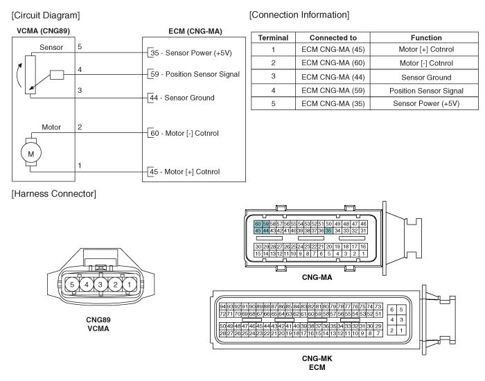
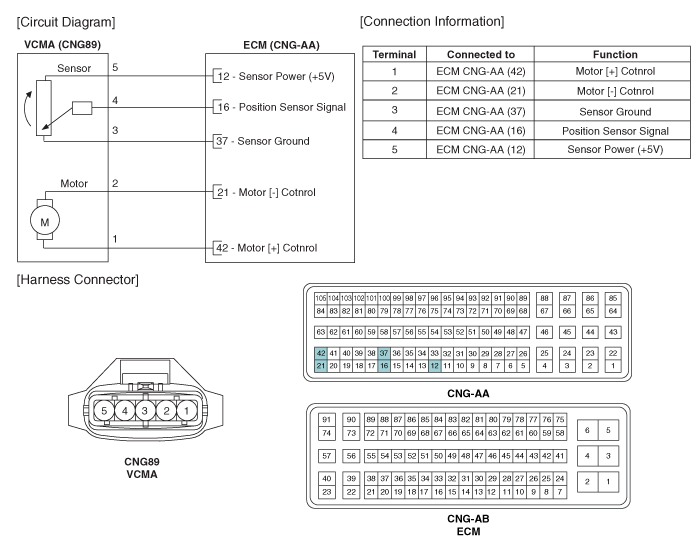
 Kia Forte: Variable Charge Motion Actuator (VCMA) Circuit diagram
Second generation YD (2014-2018) / Kia Forte TD 2014-2018 Service Manual / Engine Control / Fuel System / Engine Control System / Variable Charge Motion Actuator (VCMA) Circuit diagram
| (M/T) |

| (A/T) |

 Variable Charge Motion Actuator (VCMA) Specification
Motor
Item
Specification
Coil Resistance (Ω)
3.4 ~ 4.4 [20°C(68°F)]
Position sensor
Item
Specification
Coil Resis ...
 Variable Charge Motion Actuator (VCMA) Inspection
1.
Turn ignition switch OFF.
2.
Disconnect the VCMA connector.
3.
Check that the VCMA is not stuck by foreign ...
See also:
Tail Gate Trim Component Location
(5Door)
1. Tail gate trim
...
Front Stabilizer Bar Inspection
1.
Check the bushing for wear and deterioration.
2.
Check the front stabilizer bar for deformation.
...
DC/DC Converter Component Location
1. DC/DC Converter [200W]
...
Copyright © www.kifomanual.com 2014-2025
