 Kia Forte: Components Location
Second generation YD (2014-2018) / Kia Forte TD 2014-2018 Service Manual / Engine Control / Fuel System / Engine Control System / Components Location
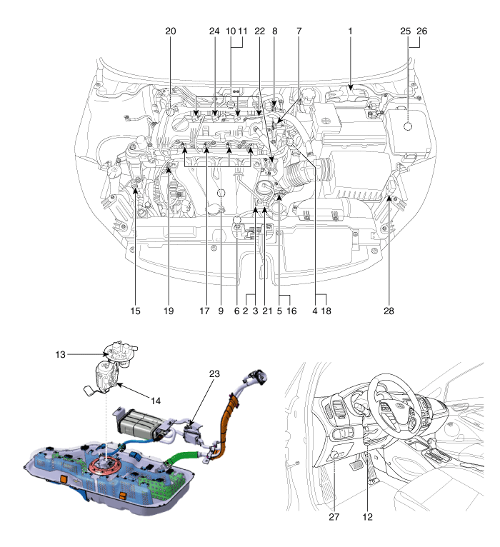
| 1. Engine Control Module (ECM) 2. Manifold Absolute Pressure Sensor (MAPS) 3. Intake Air Temperature Sensor (IATS) 4. Engine Coolant Temperature Sensor (ECTS) 5. Throttle Position Sensor (TPS) [integrated into ETC Module] 6. Crankshaft Position Sensor (CKPS) 7. Camshaft Position Sensor (CMPS) [Bank 1 / Intake] 8. Camshaft Position Sensor (CMPS) [Bank 1 / Exhaust] 9. Knock Sensor (KS) 10. Heated Oxygen Sensor (HO2S) [Bank 1 / Sensor 1] 11. Heated Oxygen Sensor (HO2S) [Bank 1 / Sensor 2] 12. Accelerator Position Sensor (APS) 13. Fuel Tank Pressure Sensor (FTPS) 14. Fuel Level Sender (FLS) |
15. A/C Pressure Transducer (APT) 16. ETC Motor [integrated into ETC Module] 17. Injector 18. Purge Control Solenoid Valve (PCSV) 19. CVVT Oil Control Valve (OCV) [Bank 1 / Intake] 20. CVVT Oil Control Valve (OCV) [Bank 1 / Exhaust] 21. Variable Intake Solenoid (VIS) Valve 22. Variable Charge Motion Actuator (VCMA) 23. Canister Close Valve (CCV) 24. Ignition Coil 25. Main Relay 26. Fuel Pump Relay 27. Data Link Connector (DLC) [16-Pin] 28. Multi-Purpose Check Connector [20-Pin] |
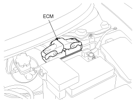
| 1. Engine Control Module (ECM) |
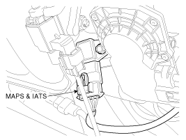
2. Manifold Absolute Pressure Sensor (MAPS) 3. Intake Air Temperature Sensor (IATS) |
|
|
|
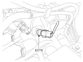
| 4. Engine Coolant Temperature Sensor (ECTS) |
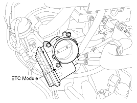
5. Throttle Position Sensor (TPS) 16. ETC Motor |
|
|
|
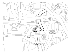
| 6. Crankshaft Position Sensor (CKPS) |
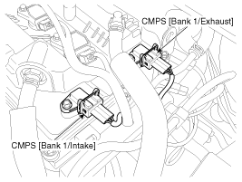
7. Camshaft Position Sensor (CMPS) [Bank 1 / Intake] 8. Camshaft Position Sensor (CMPS) [Bank 1 / Exhaust] |
|
|
|
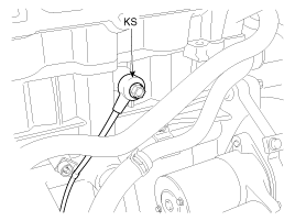
| 9. Knock Sensor (KS) |
10. Heated Oxygen Sensor (HO2S) [SULEV] 11. Heated Oxygen Sensor (HO2S) [SULEV] |
|
|
|
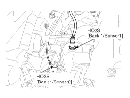
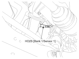
| 10. Heated Oxygen Sensor (HO2S) [Bank 1/Sensor 1] [LEV2] |
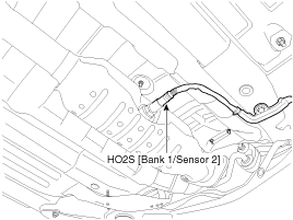
11. Heated Oxygen Sensor (HO2S) [Bank 1/Sensor 2] [LEV2] |
|
|
|
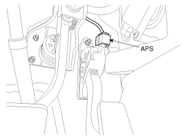
| 12. Accelerator Position Sensor (APS) |
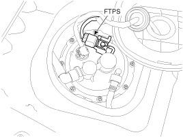
13. Fuel Tank Pressure Sensor (FTPS) |
|
|
|
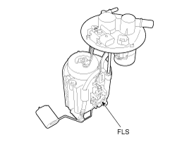
| 14. Fuel Level Sensor (FLS) |
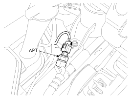
15. A/C Pressure Transducer (APT) |
|
|
|
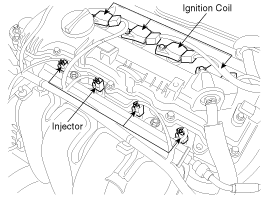
| 17. Injector 24. Ignition Coil |
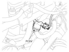
18. Purge Control Solenoid Valve (PCSV) |
|
|
|
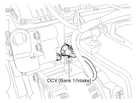
| 19. CVVT Oil Control Valve (OCV) [Bank 1 / Intake] |
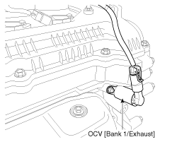
20. CVVT Oil Control Valve (OCV) [Bank 1 / Exhaust] |
|
|
|
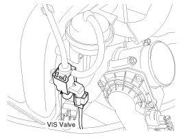
| 21. Variable Intake Solenoid (VIS) Valve |
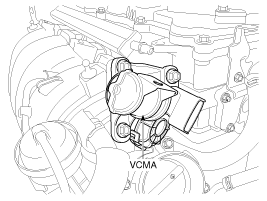
22. Variable Charge Motion Actuator (VCMA) |
|
|
|
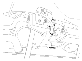
| 23. Canister Close Valve (CCV) |
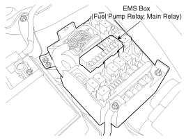
25. Main Relay 26. Fuel Pump Relay |
|
|
|
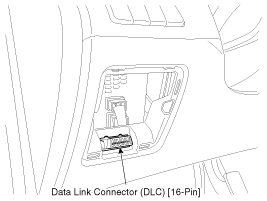
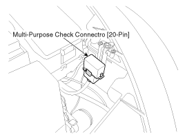
| 27. Data Link Connector (DLC) [16-Pin] |
28. Multi-Purpose Check Connector [20-Pin] |
|
|
|
 OBD-II review
1. Overview
The California Air Resources Board (CARB) began regulation of On Board
Diagnostics (OBD) for vehicles sold in California beginning with the 1988 model
year. The first phase, O ...
 ECM Terminal And Input/Output signal (M/T)
ECM Terminal Function
Connector [CNG-MA]
Pin No.
Description
Connected to
1
Ignition Coil (Cylinder #1) control output
Ignition Co ...
See also:
Exterior care
Exterior general caution
It is very important to follow the label directions when using any chemical cleaner
or polish. Read all warning and caution statements that appear on the label.
CAUTION - H ...
Power Window Switch Inspection
Power Window Main Switch Inspection
1.
Disconnect the negative (-) battery terminal.
2.
Remove the front door trim.
(Refer to Body - ...
Sunroof Deflector Replacement
1.
Open the glass fully.
2.
Remove the mounting pins (C), from the frame (B), and then remove
the deflector (A).
...
Categories
- Home
- Kia Forte BD 2019-2026 Owners Manual
- Kia Forte BD 2019-2026 Service Manual
- First Generation
- Second generation
- Kia Forte TD 2014-2018 Owners Manual
- Kia Forte TD 2014-2018 Service Manual

Copyright ® www.kifomanual.com 2014-2026