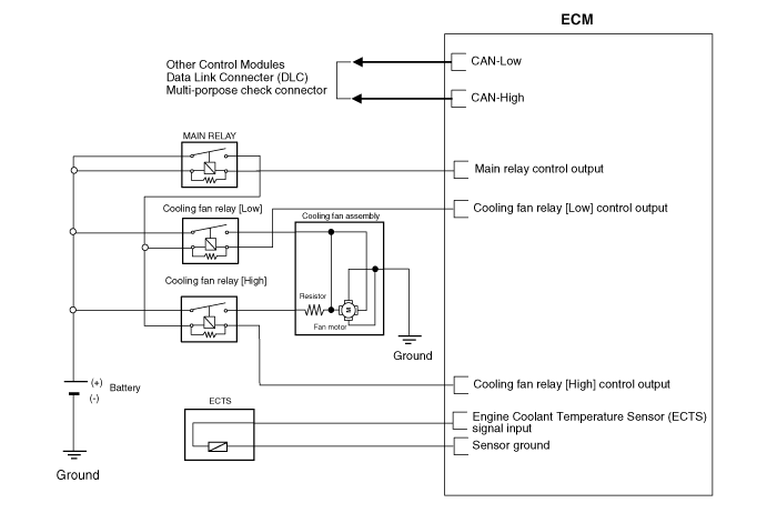
 Kia Forte: Cooling Fan Circuit Diagram
Second generation YD (2014-2018) / Kia Forte TD 2014-2018 Service Manual / Engine Mechanical System / Cooling System / Cooling Fan Circuit Diagram

 Cooling Fan Specifications
Item
Specification
Fan type
PULLER
Fan speed control
Resistor (HI-LOW-OFF)
Air flow rate [㎥/h (yd³/h)]
1,700 (2,22 ...
 Cooling Fan Removal and Installation
Cooling fan assembly
1.
Disconnect the battery "-" terminal.
2.
Remove the air duct and air cleaner assembly.
(Refer to ...
See also:
Rear Hub - Carrier Replacement
1.
Loosen the wheel nuts slightly.
Raise the vehicle, and make sure it is securely supported.
2.
Remove the rear wheel and tire (A) from ...
Electric Oil Pump Removal
1.
Disconnect the negative (-) battery terminal.
2.
Disconnect the Electric Oil Pump (EOP) connector (A).
3.
...
Rear Coil Spring Components
1. Spring upper pad
2. Spring
3. Spring lower pad
...
Copyright ® www.kifomanual.com 2014-2025
