 Kia Forte: ECM Terminal And Input/Output signal (A/T)
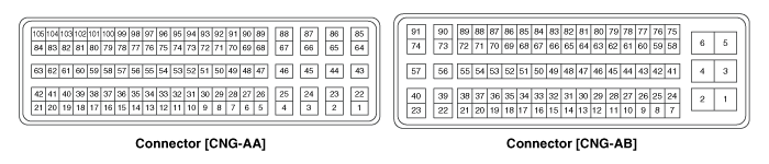
Second generation YD (2014-2018) / Kia Forte TD 2014-2018 Service Manual / Engine Control / Fuel System / Engine Control System / ECM Terminal And Input/Output signal (A/T)
| ECM Terminal Function |
Connector [CNG-AA]
| Pin No. |
Description |
Connected to |
| 1 |
Ignition Coil (Cylinder #2) control output |
Ignition Coil (Cylinder #2) [Without Immobilizer] |
| Ignition Coil (Cylinder #3) control output |
Ignition Coil (Cylinder #3) [With Immobilizer] |
|
| 2 |
- |
|
| 3 |
- |
|
| 4 |
- |
|
| 5 |
- |
|
| 6 |
- |
|
| 7 |
- |
|
| 8 |
- |
|
| 9 |
- |
|
| 10 |
- |
|
| 11 |
Camshaft Position Sensor (CMPS) [Bank 1/Intake] signal input |
Camshaft Position Sensor (CMPS) [Bank 1/Intake] |
| 12 |
Sensor power (+5V) |
Variable Charge Motion Actuator (VCMA) |
| Battery Sensor |
||
| 13 |
- |
|
| 14 |
Heated Oxygen Sensor (HO2S) [Bank 1/Sensor 2] signal input |
Heated Oxygen Sensor (HO2S) [Bank 1/Sensor 2] |
| 15 |
- |
|
| 16 |
Sensor feedback signal input |
Variable Charge Motion Actuator (VCMA) |
| 17 |
- |
|
| 18 |
- |
|
| 19 |
- |
|
| 20 |
Sensor ground |
Crankshaft Position Sensor (CKPS) |
| 21 |
Motor [-] control output |
Variable Charge Motion Actuator (VCMA) |
| 22 |
Ignition Coil (Cylinder #4) control output |
Ignition Coil (Cylinder #4) [Without Immobilizer] |
| Ignition Coil (Cylinder #1) control output |
Ignition Coil (Cylinder #1) [With Immobilizer] |
|
| 23 |
- |
|
| 24 |
- |
|
| 25 |
- |
|
| 26 |
- |
|
| 27 |
- |
|
| 28 |
- |
|
| 29 |
- |
|
| 30 |
Sensor ground |
Camshaft Position Sensor (CMPS) [Bank 1/Exhaust] |
| 31 |
Camshaft Position Sensor (CMPS) [Bank 1/Exhaust] signal input |
Camshaft Position Sensor (CMPS) [Bank 1/Exhaust] |
| 32 |
Sensor ground |
Camshaft Position Sensor (CMPS) [Bank 1/Intake] |
| 33 |
Sensor power (+5V) |
Throttle Position Sensor (TPS) 1,2 |
| 34 |
- |
|
| 35 |
Sensor ground |
Heated Oxygen Sensor (HO2S) [Bank 1/Sensor 2] |
| 36 |
- |
|
| 37 |
Sensor ground |
Variable Charge Motion Actuator (VCMA) |
| 38 |
- |
|
| 39 |
- |
|
| 40 |
- |
|
| 41 |
Crankshaft Position Sensor (CKPS) signal input |
Crankshaft Position Sensor (CKPS) |
| 42 |
Motor [+] control output |
Variable Charge Motion Actuator (VCMA) |
| 43 |
- |
|
| 44 |
- |
|
| 45 |
- |
|
| 46 |
- |
|
| 47 |
- |
|
| 48 |
- |
|
| 49 |
- |
|
| 50 |
- |
|
| 51 |
- |
|
| 52 |
- |
|
| 53 |
- |
|
| 54 |
Sensor ground |
Throttle Position Sensor (TPS) 1, 2 |
| 55 |
- |
|
| 56 |
Sensor shield ground |
Knock Sensor (KS) |
| 57 |
Immobilizer communication line |
Immobilizer control module |
| 58 |
Sensor ground |
Battery Sensor |
| 59 |
Intake Air Temperature Sensor (IATS) signal input |
Intake Air Temperature Sensor (IATS) |
| 60 |
- |
|
| 61 |
Sensor ground |
Manifold Absolute Pressure Sensor (MAPS) |
| 62 |
Sensor ground |
Engine Coolant Temperature Sensor (ECTS) |
| 63 |
Engine Coolant Temperature Sensor (ECTS) signal input |
Engine Coolant Temperature Sensor (ECTS) |
| 64 |
Ignition Coil (Cylinder #3) control output |
Ignition Coil (Cylinder #3) [Without Immobilizer] |
| Ignition Coil (Cylinder #2) control output |
Ignition Coil (Cylinder #2) [With Immobilizer] |
|
| 65 |
- |
|
| 66 |
- |
|
| 67 |
- |
|
| 68 |
- |
|
| 69 |
- |
|
| 70 |
- |
|
| 71 |
- |
|
| 72 |
- |
|
| 73 |
- |
|
| 74 |
- |
|
| 75 |
Throttle Position Sensor (TPS) 2 signal input |
Throttle Position Sensor (TPS) 2 |
| 76 |
- |
|
| 77 |
Sensor ground |
Knock Sensor (KS) |
| 78 |
- |
|
| 79 |
Battery Sensor signal |
Battery Sensor |
| 80 |
- |
|
| 81 |
- |
|
| 82 |
Manifold Absolute Pressure Sensor (MAPS) signal input
|
Manifold Absolute Pressure Sensor (MAPS) |
| 83 |
VIP (Current Pump) |
Heated Oxygen Sensor [Bank 1/Sensor 1] |
| 84 |
VG (Virtual Ground) |
Heated Oxygen Sensor [Bank 1/Sensor 1] |
| 85 |
Ignition Coil (Cylinder #1) control output |
Ignition Coil (Cylinder #1) [Without Immobilizer] |
| Ignition Coil (Cylinder #4) control output |
Ignition Coil (Cylinder #4) [With Immobilizer] |
|
| 86 |
- |
|
| 87 |
- |
|
| 88 |
- |
|
| 89 |
- |
|
| 90 |
- |
|
| 91 |
- |
|
| 92 |
- |
|
| 93 |
- |
|
| 94 |
- |
|
| 95 |
- |
|
| 96 |
Throttle Position Sensor (TPS) 1 signal input |
Throttle Position Sensor (TPS) 1 |
| 97 |
- |
|
| 98 |
Knock Sensor (KS) signal input |
Knock Sensor (KS) |
| 99 |
- |
|
| 100 |
Battery Current Direct input |
Battery Sensor |
| 101 |
- |
|
| 102 |
- |
|
| 103 |
Sensor power (+5V) |
Manifold Absolute Pressure Sensor (MAPS) |
| 104 |
VRC (Current Adjust) |
Heated Oxygen Sensor [Bank 1/Sensor 1] |
| 105 |
VN (NERNST Cell Voltage) |
Heated Oxygen Sensor [Bank 1/Sensor 1] |
Connector [CNG-AB]
| Pin No. |
Description |
Connected to |
| 1 |
Power ground |
Chassis Ground |
| 2 |
Power ground |
Chassis Ground |
| 3 |
Battery power (B+) |
Main Relay |
| 4 |
Power ground |
Chassis Ground |
| 5 |
Battery power (B+) |
Main Relay |
| 6 |
Battery power (B+) |
Main Relay |
| 7 |
- |
|
| 8 |
- |
|
| 9 |
- |
|
| 10 |
Brake Test Switch signal input |
Brake Switch |
| 11 |
A/C Compressor switch signal output |
A/C Compressor switch |
| 12 |
- |
|
| 13 |
Sensor power (+5V) |
Fuel Tank Pressure Sensor (FTPS) |
| A/C Pressure Transducer (APT) |
||
| 14 |
- |
|
| 15 |
Electrical load signal input |
Alternator |
| 16 |
Alternator PWM control output |
Alternator |
| 17 |
- |
|
| 18 |
Cooling Fan Relay [High] control output |
Cooling Fan Relay [High] |
| 19 |
Immobilizer Lamp control output |
Immobilizer Lamp [Without Button Engine Start System] |
| 20 |
ETC Motor [+] control output |
ETC Motor |
| 21 |
ETC Motor [-] control output |
ETC Motor |
| 22 |
Electrical load [Wiper] signal input |
Wiper [Low] Relay |
 ECM Terminal And Input/Output signal (M/T)
ECM Terminal Function
Connector [CNG-MA]
Pin No.
Description
Connected to
1
Ignition Coil (Cylinder #1) control output
Ignition Co ...
 Engine Control Module (ECM) Circuit Diagram
(M/T)
(A/T)
...
See also:
Hazard Lamp Switch Installation
1.
Install the hazard switch.
2.
Install the center fascia panel.
...
Engine Mounting Components
1. Transaxle mounting bracket
2. Roll rod bracket
3. Engine mounting bracket
4. Engine mounting support bracket
...
Installation
1.
Install the multifunction switch.
2.
Install the clock spring.
3.
Install the steering column upper and lowe ...
Categories
- Home
- Kia Forte BD 2019-2026 Owners Manual
- Kia Forte BD 2019-2026 Service Manual
- First Generation
- Second generation
- Kia Forte TD 2014-2018 Owners Manual
- Kia Forte TD 2014-2018 Service Manual

Copyright ® www.kifomanual.com 2014-2026