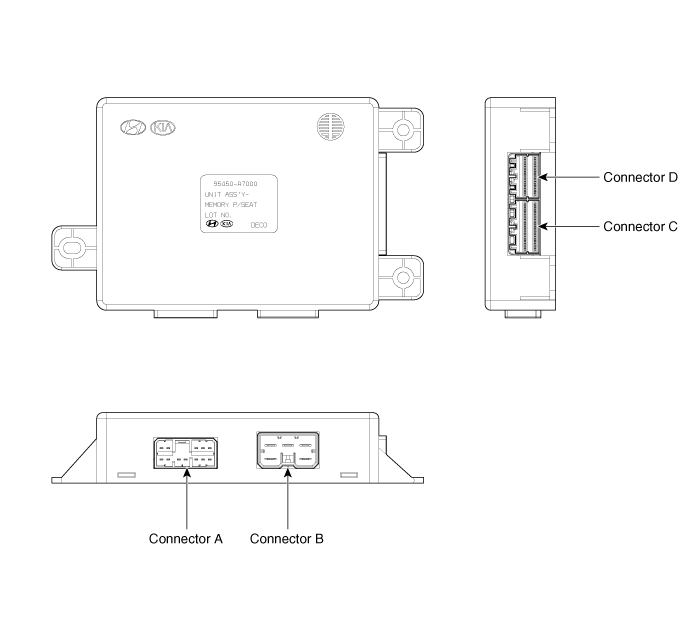
 Kia Forte: Components

Input/Output Specification

IMS input/output pin information
| No. |
Signal Name |
I/O |
Contents |
Remark |
| A1 |
- |
- |
- |
|
| A2 |
FRT height motor up |
O |
Front height motor up output |
|
| A3 |
RR height motor up |
O |
Rear height motor up output |
|
| A4 |
Recline motor FWD |
O |
Recline motor Forward output |
|
| A5 |
Slide motor FWD |
O |
Slide motor Forward output |
|
| A6 |
- |
- |
- |
|
| A7 |
FRT height motor down |
O |
Front height motor down output |
|
| A8 |
- |
- |
- |
|
| A9 |
- |
- |
- |
|
| A10 |
RR height motor down |
O |
Rear height motor down output |
|
| A11 |
Recline motor BWD |
O |
Recline motor backward output |
|
| A12 |
Slide motor BWD |
O |
Slide motor backward output |
|
| B1 |
B+(Power) |
I |
Power B+ for operating motor |
|
| B2 |
GND (Power) |
I |
Power GND for operating motor |
|
| B3 |
B+(Power) |
I |
Power B+ for operating motor |
|
| B4 |
- |
- |
- |
|
| B5 |
GND (Power) |
I |
Power GND for operating motor |
|
| C1 |
- |
- |
- |
|
| C2 |
- |
- |
- |
|
| C3 |
Slide FWD manual switch |
I |
Slide forward manual switch input |
On : GND |
| C4 |
Recline FWD manual switch |
I |
Recline forward manual switch input |
On : GND |
| C5 |
FRT height up manual switch |
I |
Front height up manual switch input |
On : GND |
| C6 |
RR height up manual switch |
I |
Rear height up manual switch input |
On : GND |
| C7 |
Slide motor sensor |
I |
Slide motor sensor input |
Pulse signal |
| C8 |
Recline motor sensor |
I |
Recline motor sensor input |
Pulse signal |
| C9 |
FRT height motor sensor |
I |
Front height motor sensor input |
Pulse signal |
| C10 |
Sensor Vcc(Seat) |
O |
VCC for operating sensor |
5V |
| C11 |
- |
- |
- |
|
| C12 |
- |
- |
- |
|
| C13 |
Slide RR manual switch |
I |
Slide rear manual switch input |
ON : GND |
| C14 |
Recline RR manual switch |
I |
Recline rear manual switch input |
ON : GND |
| C15 |
FRT height down manual switch |
I |
Front height down manual switch input |
ON : GND |
| C16 |
RR height down manual switch |
- |
Rear height down manual switch input |
ON : GND |
| C17 |
- |
- |
- |
|
| C18 |
- |
- |
- |
|
| C19 |
- |
- |
- |
|
| C20 |
- |
- |
- |
|
| D1 |
SET switch |
I |
SET switch input |
ON : GND |
| D2 |
RR height up sensor |
I |
Rear height up motor sensor |
Pulse signal |
| D3 |
SW1 switch |
I |
SW1 switch input |
ON : GND |
| D4 |
CAN high |
I/O |
CAN high BUS |
|
| D5 |
CAN low |
I/O |
CAN low BUS |
|
| D6 |
SW2 switch |
I |
SW2 switch input |
ON : GND |
| D7 |
IGN1 |
I |
IGN1 input |
BAT |
| D8 |
B+(ECU) |
I |
ECU power input |
BAT |
| D9 |
GND(SIGNAL) |
I |
Sinal ground |
|
| D10 |
- |
- |
- |
|
| D11 |
- |
- |
- |
|
| D12 |
- |
- |
- |
|
| D13 |
- |
- |
- |
|
| D14 |
- |
- |
- |
|
| D15 |
- |
- |
- |
|
| D16 |
- |
- |
- |
|
 Operation
Control Specification
1.
MANUAL Operation
(1)
MANUAL Seat Operation SEAT is to be operated by MANUAL
switch Input of SEAT. SLI ...
 Circuit Diagram
...
See also:
Inspection
1.
Remove the air cleaner assembly.
(Refer to Engine Mechanical System - "Air Cleaner")
2.
Remove the battery and battery tray ...
Piston and Connecting Rod Disassembly
Engine removal is required for this procedure.
ŌĆó
Use fender covers to avoid damaging pain ...
Front Seat Assembly Replacement
ŌĆó
When removing or installing the front passenger seat,
be sure to initialize the Weig ...
Copyright ® www.kifomanual.com 2014-2026
