
 Kia Forte: Instrument Cluster Circuit Diagram
Second generation YD (2014-2018) / Kia Forte TD 2014-2018 Service Manual / Body Electrical System / Indicators And Gauges / Instrument Cluster Circuit Diagram
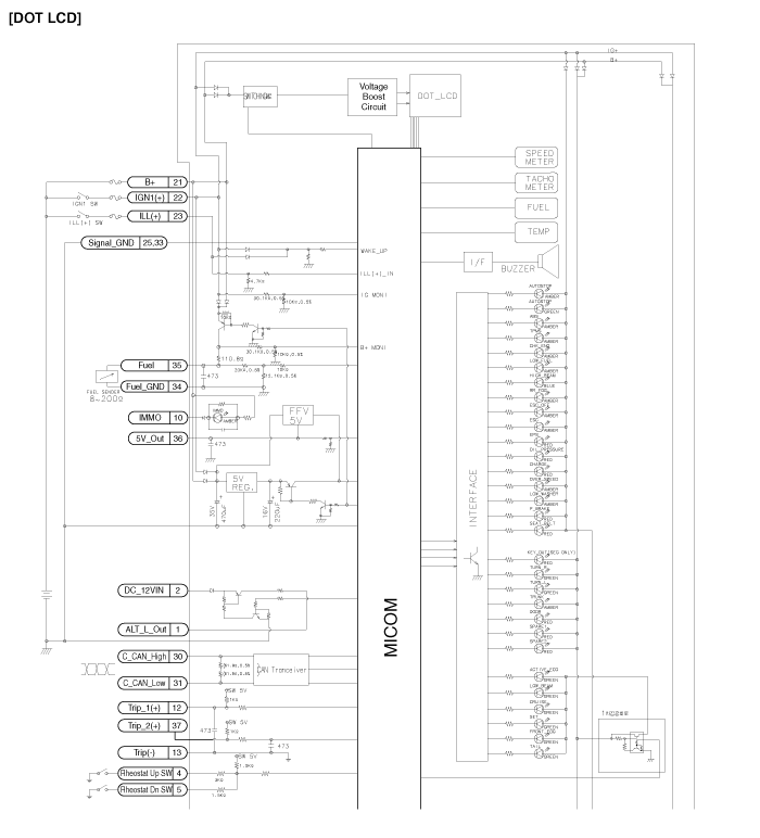
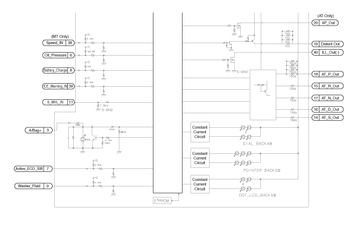
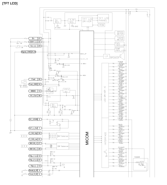
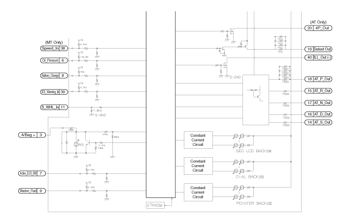
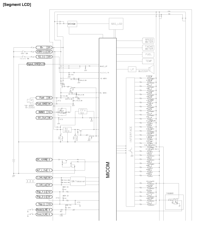
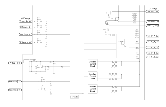
 Instrument Cluster Description
Cluster Variant Coding
As we have more options (ESC, TPMS, etc.) in the car, the dashboard now
have more information to display depending on the chosen options.
For this reason, we need ...
 Instrument Cluster Removal
1.
Disconnect the negative (-) battery terminal.
2.
Remove the cluster fascia panel.
(Refer to Body - "Cluster Fascia Panel") ...
See also:
Fuse/relay panel description
Inside the fuse/relay panel covers, you can find the fuse/relay label describing
fuse/relay name and capacity.
✽ NOTICE
Not all fuse panel descriptions in this manual may be applicable t ...
Service Standard
Item
Specification
Ignition Timing (°)
BTDC 5 ± 10
Idle Speed (rpm)
A/C OFF
Neutral, N, P-range
640 ± 100
D-range
...
26 Brake Control Solenoid Valve(26/B_VFS) Inspection
1.
Turn ignition switch OFF.
2.
Disconnect the Solenoid valve connector.
3.
Measure resistance between sensor ...
Categories
- Home
- Kia Forte BD 2019-2026 Owners Manual
- Kia Forte BD 2019-2026 Service Manual
- First Generation
- Second generation
- Kia Forte TD 2014-2018 Owners Manual
- Kia Forte TD 2014-2018 Service Manual

Copyright © www.kifomanual.com 2014-2026