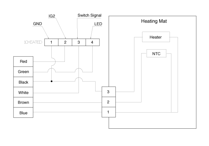
 Kia Forte: System Circuit Diagram
Second generation YD (2014-2018) / Kia Forte TD 2014-2018 Service Manual / Steering System / Steering wheel / Heated Steering wheel / System Circuit Diagram


Terminal Function
| No. |
Function |
Wire color |
| 1 |
GND |
Back |
| 2 |
IG2 |
Red |
| 3 |
Switch Signal |
White |
| 4 |
LED |
Green |
Terminal Function
| No. |
Function |
Wire color |
| 1 |
GND |
Back |
| 2 |
NTC |
Brown |
| 3 |
Heater (+) |
Blue |
 Heated Steering wheel
Heated pads to grip the steering grip makes the fever.
1.
Heated control unit
2.
Heated pad
Specifications
...
 Inpection
1.
Measure a resistance of NTC and Heated pad.
A.
NTC resistance - 10.0 kΩ ┬▒ 10% (25┬░C)
B.
...
See also:
Hazard Lamp Switch Installation
1.
Install the hazard switch.
2.
Install the center fascia panel.
...
Auto Head Lamp Leveling Unit Removal
1.
Remove the head lamp leveling unit connector (A).
2.
Remove the head lamp leveling unit (B) after loosening the mounting
bolts.
...
Door Switch Description
Via the seat belt/Door switch, the ISG function can detect that the driver
has fastened the seat belt/door. If the driver has not fastened the seat belt/door,
the ISG function reacts as follo ...
Copyright ® www.kifomanual.com 2014-2026
