 Kia Forte: Replacement
Problems And Replacement Parts:
| Problem |
Part set |
Scan tool required? |
| All keys have been lost |
Blank key (4) |
YES |
| Antenna coil unit does not work |
Antenna coil unit |
NO |
| ECM does not work |
ECM |
YES |
| Ignition switch does not work |
Ignition switch with Antenna coil unit |
YES |
| Unidentified vehicle specific data occurs |
Key, ECM |
YES |
| Immobilizer unit does not work |
Immobilizer unit |
YES |
Replacement Of Ecm And Immobilizer
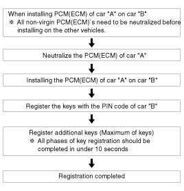
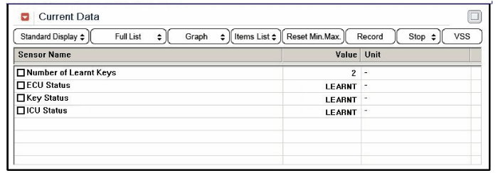
In case of a defective ECM, the unit has to be replaced with a "virgin"
or "neutral" ECM. All keys have to be taught to the new ECM. Keys, which are
not taught to the ECM, are invalid for the new ECM (Refer to key teaching procedure).
The vehicle specific data have to be left unchanged due to the unique programming
of transponder.
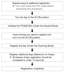
In case of a defective Immobilizer, it needs teaching the Immobilizer.
A new Immobilizer device replaces the old one and Immobilizer need teaching.
| 1. |
Things to remember before a replacement (ECM)
|
| 2. |
Things to remember before a replacement (Keys & Additional registration)
|
Neutralizing Of ECM
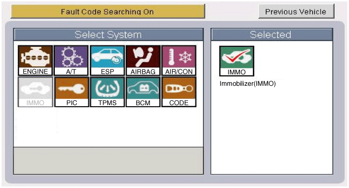
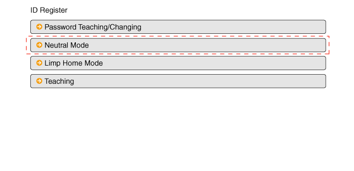
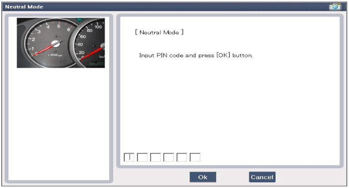
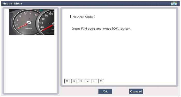
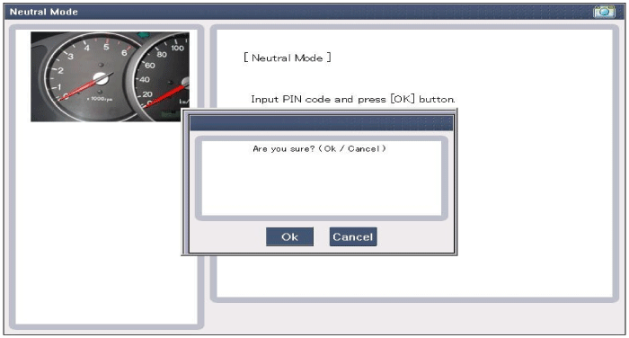
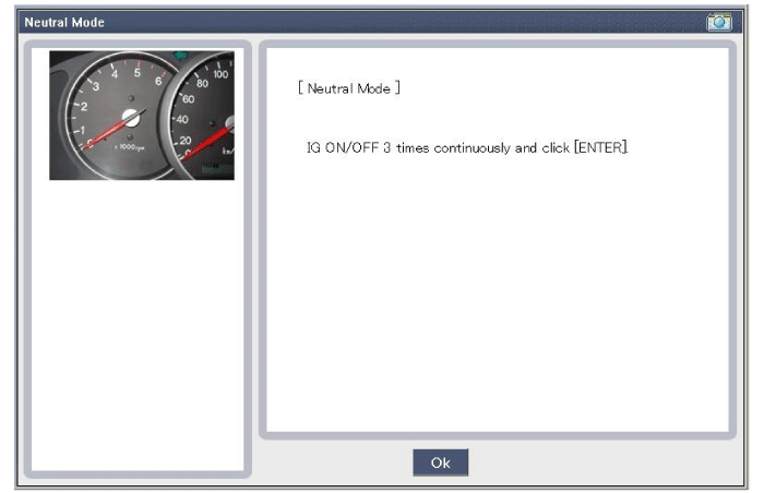
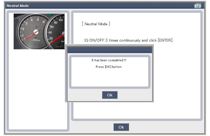
The ECM can be set to the "neutral" status by a tester.
A valid ignition key is inserted and after ignition on is recorded, the
ECM requests the vehicle specific data from the tester. The communication messages
are described at "Neutral Mode" After successfully receiving the data, the ECM
is neutralized.
The ECM remains locked. Neither the limp home mode nor the "twice ignition
on" function, is accepted by the ECM.
The teaching of keys follows the procedure described for the virgin ECM.
The vehicle specific data have to be unchanged due to the unique programming
of the transponder. If data should be changed, new keys with a virgin transponder
are requested.
This function is for neutralizing the ECM and Key. Ex) when lost key,
Neutralize the ECM then teach keys.
(Refer to the Things to do when Key & PIN Code the ECM can be set to the
"neutral" status by a scanner. If wrong vehicle specific data have been sent
to immobilizer three times continuously or intermittently, the immobilizer will
reject the request to enter neutral mode for one hour. Disconnecting the battery
or other manipulation cannot reduce this time. After connecting the battery
the timer starts again for one hour.
|

 Limp Home Function
1.
Limp Home By Tester
If the ECM detects the fault of the Immobilizer or transponder,
the ECM will allow limp home function of the immobilizer. Limp home
is o ...
 Immobilizer Control Unit Removal
1.
Disconnect the negative (-) battery terminal.
2.
Remove the crash pad lower panel.
(Refer to Body - "Crash Pad Lower Panel" ...
See also:
Description
The Vehicle Information System is a Telematics service that ensures comfortable
and enjoyable driving by providing safety, security, and vehicle diagnostic
information, with the option of usi ...
Front Hub / Knuckle Replacement
1.
Loosen the wheel nuts slightly.
Raise the vehicle, and make sure it is securely supported.
2.
Remove the front wheel and tire (A ...
Component Location
[Engine Room]
1. Receiver Drier
2. Condenser
3. Ambient Temperature Sensor
4. Compressor
5. Discharge Hose
6. Suction & Liquid Tube Assembly
7. Servic ...
Copyright ® www.kifomanual.com 2014-2026

