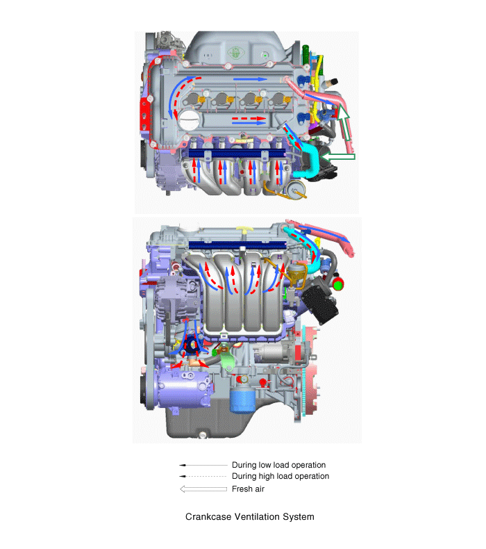
 Kia Forte: Schematic Diagram

 Inspection
1.
After disconnecting the vapor hose from the PCV valve, remove
the PCV valve.
2.
Reconnect the PCV valve to the vapor hose.
...
See also:
Inhibitor Switch Circuit Diagram
...
Battery Sensor Installation
1.
Install in the reverse order of removal.
Battery sensor cable installation
bolt: 10.8 ~ 13.7 N.m (1.1 ~ 1.4 kgf.m, 8.0 ~10.1
lb-ft)
...
Exhaust Manifold Components
1. Heat protector
2. Exhaust manifold gasket
3. Exhaust manifold
4. Exhaust manifold stay
...
Categories
- Home
- Kia Forte BD 2019-2026 Owners Manual
- Kia Forte BD 2019-2026 Service Manual
- First Generation
- Second generation
- Kia Forte TD 2014-2018 Owners Manual
- Kia Forte TD 2014-2018 Service Manual

Copyright ® www.kifomanual.com 2014-2026