
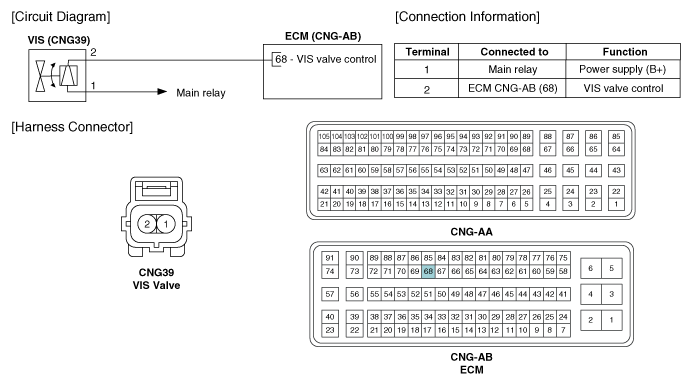
 Kia Forte: Variable Intake Solenoid (VIS) Valve Circuit Diagram
Second generation YD (2014-2018) / Kia Forte TD 2014-2018 Service Manual / Engine Control / Fuel System / Engine Control System / Variable Intake Solenoid (VIS) Valve Circuit Diagram
| (M/T) |
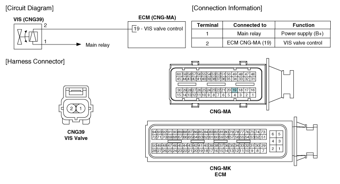
| (A/T) |
 Variable Intake Solenoid (VIS) Valve Specification
Item
Specification
Coil resistance (Ω)
30.0 ~ 35.0 [20°C(68°F)]
...
 Variable Intake Solenoid (VIS) Valve Inspection
1.
Turn the ignition switch OFF.
2.
Disconnect the VIS valve connector.
3.
Measure resistance between VIS valve ...
See also:
Parking Assist Sensor Removal
[Front Bumper]
1.
Disconnect the negative (-) battery terminal.
2.
Remove the front bumper cover.
(Refer to Body - "Front Bumpe ...
Shift Lever Inspection
1.
Check operating of lever of T/M side when operating shift lever
after assembly.
2.
When shift lever to "R" position, check th ...
DC/DC Converter Removal
1.
Disconnect the battery negative (-) cable.
2.
Remove the crash pad lower panel.
(Refer to Body - Crash pad lower panel.)
...
Categories
- Home
- Kia Forte BD 2019-2026 Owners Manual
- Kia Forte BD 2019-2026 Service Manual
- First Generation
- Second generation
- Kia Forte TD 2014-2018 Owners Manual
- Kia Forte TD 2014-2018 Service Manual

Copyright © www.kifomanual.com 2014-2026