 Kia Forte: Emergency starting
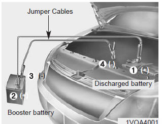
Connect cables in numerical order and disconnect in reverse order.
Jump starting
Jump starting can be dangerous if done incorrectly. Therefore, to avoid harm to yourself or damage to your vehicle or battery, follow these jump starting procedures. If in doubt, we strongly recommend that you have a competent technician or towing service jump start your vehicle.
CAUTION - 12 volt battery
Use only a 12-volt jumper system. You can damage a 12-volt starting motor, ignition system, and other electrical parts beyond repair by use of a 24- volt power supply (either two 12-volt batteries in series or a 24-volt motor generator set).
WARNING - Battery
Never attempt to check the electrolyte level of the battery as this may cause the battery to rupture or explode.
WARNING - Frozen batteries
Do not attempt to jump start the vehicle if the discharged battery is frozen or if the electrolyte level is low as the battery may rupture or explode.
WARNING - Battery
Keep all flames or sparks away from the battery. The battery produces hydrogen gas which will explode if exposed to flame or sparks.
WARNING - Sulfuric acid risk
When jump starting your vehicle be careful not to get acid on yourself, your clothing or on the vehicle. Automobile batteries contain sulfuric acid. This is poisonous and highly corrosive.
Jump starting procedure
1.Make sure the booster battery is 12-volt and that its negative terminal is grounded.
2.If the booster battery is in another vehicle, do not allow the vehicles to touch.
3.Turn off all unnecessary electrical loads.
4.Connect the jumper cables in the exact sequence shown in the illustration.
First connect one end of a jumper cable to the positive terminal of the discharged battery (1), then connect the other end to the positive terminal on the booster battery (2).
Proceed to connect one end of the other jumper cable to the negative terminal of the booster battery (3), then the other end to a solid, stationary, metallic point (for example, the engine lifting bracket) away from the battery (4). Do not connect it to or near any part that moves when the engine is cranked.
Do not allow the jumper cables to contact anything except the correct battery terminals or the correct ground. Do not lean over the battery when making connections.
CAUTION - Battery cables
Do not connect the jumper cable from the negative terminal of the booster battery to the negative terminal of the discharged battery. This can cause the discharged battery to overheat and crack, releasing battery acid.
5.Start the engine of the vehicle with the booster battery and let it run at 2,000 rpm, then start the engine of the vehicle with the discharged battery.
If the cause of your battery discharging is not apparent, you should have your vehicle checked by an authorized Kia dealer.
Push-starting
Your manual transaxle-equipped vehicle should not be push-started because it might damage the emission control system.
Vehicles equipped with automatic transaxle cannot be push-started. Follow the directions in this section for jump-starting.
WARNING - Tow starting vehicle
Never tow a vehicle to start it because the sudden surge forward when the engine starts could cause a collision with the tow vehicle.
 Emergency while driving
In an emergency situation while the vehicle is in motion, you are able to turn
the engine off and to the ACC position by pressing the ENGINE START/STOP button
for more than 2 seconds or 3 times succ ...
 Engine overheat
If your temperature gauge indicates overheating, you will experience a loss of
power, or hear loud pinging or knocking, the engine is probably too hot. If this
happens, you should: 1.Pull off the ro ...
See also:
Specifications
Fuel Delivery System
Items
Specification
Fuel Tank
Capacity
50 lit. (13.2 U.S.gal., 52.8 U.S.qt., 44.0 Imp.qt.)
Fuel Filter
Ty ...
Master Cylinder
Components
1. Reservoir cap
2. Reservoir
3. Grommet
4. Master cylinder
...
SS-A Solenoid Valve(ON/OFF) Specifications
ON/OFF Solenoid Valve(SS-A, SS-B)
▷ Control type : Normal low type
Control pressure kpa (kgf/cm², psi)
490.33(5.0, 71.12)
Internal resistance(Ω ...
Categories
- Home
- Kia Forte BD 2019-2026 Owners Manual
- Kia Forte BD 2019-2026 Service Manual
- First Generation
- Second generation
- Kia Forte TD 2014-2018 Owners Manual
- Kia Forte TD 2014-2018 Service Manual
