 Kia Forte: Description
Burglar Alarm State [B/A State]
B/A State
|
Description
|
DISARM
|
| 1. |
In "DISARM" state, no vehicle start inhibition. So, when
door, hood, or Trunk is opened, there is no alarm sound and
flashing.
|
| 2. |
If the battery is disconnected while the state is not
"ARM/ARMWAIT/ALARM/REARM", B/A state is set to "DISARM" state.
|
| 3. |
In ŌĆ£DISARMŌĆØ state, security indicator keeps blinking.
|
|
ARMWAIT
|
| 1. |
In "ARMWAIT" state, when timer ŌĆ£30sec." is running, if
this timer reaches ŌĆ£30secŌĆØ, state transitions to "ARM" state.
|
| 2. |
If the battery is disconnected while the state is "ARMWAIT",
B/A state is set to "ARMWAIT" state and timer "30sec" is restarted.
|
| 3. |
In ŌĆ£ARMWAITŌĆØ state, security indicator keeps on.
|
|
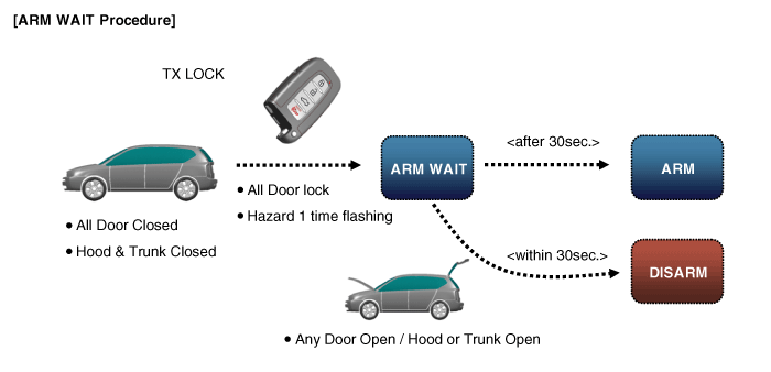
※ Remark: On Smart key system, it works the same way with passive lock
B/A State
|
Description
|
AUTO LOCK TIMER 1
|
| 1. |
In "AUTOLOCKTIMER1" state, timer ŌĆ£30sec."is running. If
this timer expired, the auto lock command is generated ŌĆ£Lock
commandŌĆØ.
|
| 2. |
When ŌĆ£Lock commandŌĆØ operated, All Door changed lock and
closed then B/A state changes ŌĆ£AUTOLOCKTIMER1ŌĆØ to ŌĆ£ARMWAIT
|
| 3. |
In "AUTOLOCKTIMER1" state, Security Indicator keeps blinking.
In "AUTOLOCKTIMER1" state, timer ŌĆ£30sec."is running. If this
timer expired, the auto lock command is generated ŌĆ£Lock commandŌĆØ.
When ŌĆ£Lock commandŌĆØ operated, All Door changed lock and closed
then B/A state changes ŌĆ£AUTOLOCKTIMER1ŌĆØ to ŌĆ£ARMWAIT
|
|
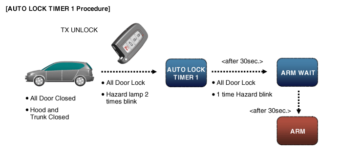
※ Remark: On Smart key system, it works the same way with passive unlock
B/A State
|
Description
|
AUTO LOCK TIMER 2
|
| 1. |
In "AUTOLOCKTIMER2" state, when timer ŌĆ£30sec."is running,
if this timer expired, the auto lock command is generated ŌĆ£Lock
commandŌĆØ.
|
| 2. |
All doors are Locked, Hood is closed and Trunk is closed
when ŌĆ£Lock commandŌĆØ operated, then B/A state changes toŌĆ£AUTOLOCKTIMER2ŌĆØ
when ŌĆ£Lock CommandŌĆØ generated with Hood open.
|
| 3. |
When ŌĆ£Unlock commandŌĆØ operated on the condition of All
Door closed and Hood open, B/A state changes to ŌĆ£AUTOLOCKTIMER2ŌĆØ.
|
| 4. |
In "AUTOLOCKTIMER2" state, Security Indicator keeps blinking.
|
|
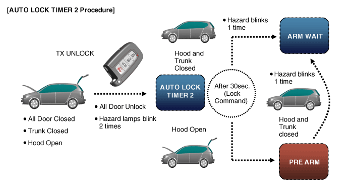
※ Remark: On Smart key system, it works the same way with passive unlock
B/A State
|
Description
|
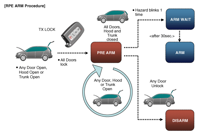
PRE ARM
|
| 1. |
The "PREARM" state is when user try to change to arm but
pre-condition are not satisfied (door open, trunk open, or hood
open).
|
| 2. |
B/A state changes to ŌĆ£PREARMŌĆØ when TX Lock command occurs
with any door Open, Hood or Trunk Open.
|
| 3. |
B/A state changes to ŌĆ£PREARMŌĆØ when ŌĆ£30sec.ŌĆØ timer expired
inŌĆ£AUTOLOCKTIMER2ŌĆØwith Hood or Trunk Open
|
| 4. |
The ŌĆ£PREAMRŌĆØ state changes to ŌĆ£ARMŌĆØ when all doors closed,
All doors locked and Hood and Trunk closed.
|
| 5. |
The ŌĆ£PREAMRŌĆØ state changes to ŌĆ£DISARMŌĆØ when Any Door Unlock
|
| 6. |
In this state, Security indicator keeps blinking.
|
|
B/A State
|
Description
|
RE ARM
|
| 1. |
In "REARM" state, if the vehicle intrusion is detected,
flashing and sound is restarted, again and state transitions
to "ALARM" state.
|
| 2. |
B/A state changes to ŌĆ£REARMŌĆØ after the timer ŌĆ£27sec.ŌĆØ
expires in ŌĆ£ALARMŌĆØ state with All doors closed and lock.
|
| 3. |
Security Indicator keeps blinking.
|
|
B/A State
|
Description
|
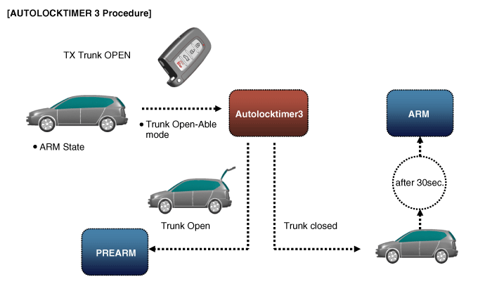
AUTOLOCK TIMER3
|
| 1. |
B/A state changes to ŌĆ£AUTOLockTIMER3ŌĆØ, when TX-Trunk command
operated.
|
| 2. |
B/A state changes ŌĆ£AUTOLOCKTIMER3ŌĆØ to ŌĆ£ARMWAITŌĆØ, when
the ŌĆ£30sec.ŌĆØ timer expires with all doors lock and closed.
|
| 3. |
B/A state changes ŌĆ£AUTOLOCKTIMER3ŌĆØ to ŌĆ£DISARMŌĆØ, when any
door open.
|
| 4. |
In "AUTOLOCKTIMER3" state, timer ŌĆ£30sec.ŌĆ£ timer is running.
If this timer expired, state transits to "PREARM" state with
Trunk Open.
|
| 5. |
In this state, Security indicator keeps blinking
|
|
1. Hood switch
2. Burglar horn
3. BCM and RF antenna
4. Key warning switch
5. Front door switch
6. Front door lock actuator & switch
7. Rear door lock actuator &am ...
Front Door Lock Module Inspection
1.
Remove the front door trim.
(Refer to Body - "Front Door Trim")
2.
Remove the front d ...
See also:
Battery Sensor Installation
1.
Install in the reverse order of removal.
Battery sensor cable installation
bolt: 10.8 ~ 13.7 N.m (1.1 ~ 1.4 kgf.m, 8.0 ~10.1
lb-ft)
...
Operation
Function Of Safety Power Window
When all door (Front, Rear) power window auto-up switch is operated, safety
function is activated.
1.
Safety function condition
...
Instrument Cluster Circuit Diagram
...
 Component Location
 Inspection