 Kia Forte: Power Seat Control Switch Inspection
Second generation YD (2014-2018) / Kia Forte TD 2014-2018 Service Manual / Body Electrical System / Seat Electrical / Power Seat Control Switch Inspection
| 1. |
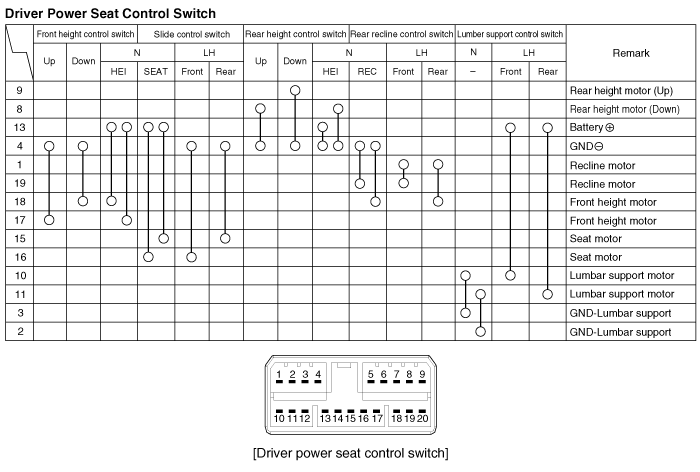
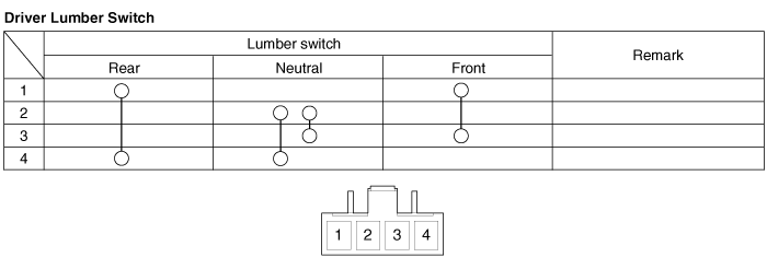
With the power seat switch in each position, make sure that continuity
exists between the terminals below. If continuity is not as specified,
replace the power seat switch.
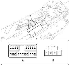
A : Power seat control switch
B : Lumbar support switch
|
 Power Seat Control Switch Removal
1.
Disconnect the negative (-) battery terminal.
2.
Remove the seat side cover (A).
3.
Disconnect the p ...
See also:
Removal
1.
Disconnect the battery negative cable, and wait for at least thirty
seconds before beginning work.
2.
Remove the seat belt after pushin ...
Warning Lamp Activation
Warning Lamp Behavior after Ignition
On
As soon as the operating voltage is applied to the SRSCM ignition input,
the SRSCM activates the warning lamp for a LED lamp check.
T ...
Brake Booster Vacuum Pressure Sensor Description
In order to ensure adequate brake power assistance in every situation,
the brake booster is equipped with a partial vacuum sensor. The brake booster
vacuum pressure sensor is located beside t ...
Copyright © www.kifomanual.com 2014-2025


