 Kia Forte: Heater & A/C Control Unit (DATC) Self Diagnosis
Second generation YD (2014-2018) / Kia Forte TD 2014-2018 Service Manual / Heating,Ventilation, Air Conditioning / Controller / Heater & A/C Control Unit (DATC) Self Diagnosis
| 1. |
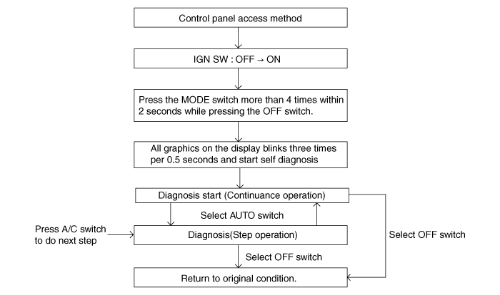
Self-diagnosis process
|
| 2. |
How to read self-diagnostic code
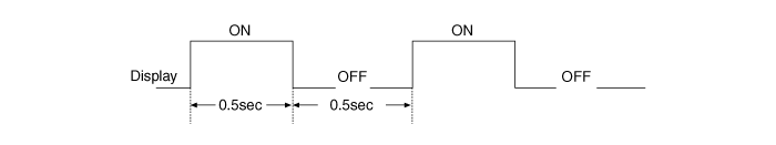
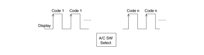
After the display panel blinks three times every 0.5 second, the
corresponding fault code blinks on the setup temperature display panel
every 0.5 second and will show two figures. Codes are displayed in numerical
format
Fault code
|
| 3. |
Fault code display
|

| 4. |
If fault codes are displayed when checking, inspect for malfunction
causes by referring to fault codes.
|
| 5. |
Fail safe
|
 Heater & A/C Control Unit (DATC) Component
Connector Pin Function
Connector
No.
Description
Connector
No.
Description
A
1
Illumination (+) (Tail)
A
...
 Heater & A/C Control Unit (DATC) Replacement
1.
Remove the audio unit.
(Refer to Body Electrical System - "Audio Unit")
2.
After loosening the mounting screws, remove the ...
See also:
Inspection
1.
Check for damage to boot.
2.
Check for deformation to clutch release fork.
3.
Check for deformation to clutc ...
Compressor Components
1. Center Bolt
2. Hub Bolt
3. Disc & Hub Assembly
4. Snap Ring
5. Pulley
6. Compressor Assembly
7. Electric Control Valve (ECV)
...
Shift Lever Removal
1.
Remove the floor console assembly.
(Refer to Body - "Floor Console")
2.
Remove the air duct.
3.
...
Categories
- Home
- Kia Forte BD 2019-2026 Owners Manual
- Kia Forte BD 2019-2026 Service Manual
- First Generation
- Second generation
- Kia Forte TD 2014-2018 Owners Manual
- Kia Forte TD 2014-2018 Service Manual

Copyright ® www.kifomanual.com 2014-2026