 Kia Forte: On-vehicle Inpection
| ŌĆó
|
First of all, check for DTCs. If a DTC is present, perform
troubleshooting in accordance with the procedure for that DTC.
(Refer to DTC guide)
|
|
| ŌĆó
|
Check that the battery cables are connected to the correct
terminals.
|
| ŌĆó
|
Disconnect the battery cables when the battery is given
a quick charge.
|
| ŌĆó
|
Never disconnect the battery while the engine is running.
|
|
|
1. |
Check The Battery Terminals And Fuses
|
(1) |
Check that the battery terminals are not loose or corroded.
|
|
(2) |
Check the fuses for continuity.
|
|
|
2. |
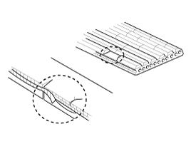
Inspect Drive Belt
|
(1) |
Visually check the belt for excessive wear, frayed cords
etc.
If any defect has been found, replace the drive belt.
|
ŌĆó |
Cracks on the rib side of a belt are considered
acceptable. If the belt has chunks missing from
the ribs, it should be replaced.
|
|
|
|
|
3. |
Drive belt tension measurement and adjustment (Refer to Engine
Mechanical System - "Drive Belt")
|
|
4. |
Visually Check Alternator Wiring And Listen For Abnormal Noises
|
(1) |
Check that the wiring is in good condition.
|
|
(2) |
Check that there is no abnormal noise from the alternator
while the engine is running.
|
|
|
5. |
Check Discharge Warning Light Circuit
|
(1) |
Warm up the engine and then turn it off.
|
|
(2) |
Turn off all accessories.
|
|
(3) |
Turn the ignition switch "ON". Check that the discharge
warning light is lit.
|
|
(4) |
Start the engine. Check that the light is lit.
If the light does not go off as specified, troubleshoot
the discharge light circuit.
|
|
| [Electrical Specified Value Inspection] |
|
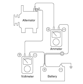
1. |
Voltage Drop Test Of Alternator Output Wire
This test determines whether or not the wiring between the alternator
"B" terminal and the battery (+) terminal is good by the voltage drop
method.
|
(1) |
Preparation
| A. |
Turn the ignition switch to "OFF".
|
| B. |
Disconnect the output wire from the alternator
"B" terminal. Connect the (+) lead wire of ammeter to
the "B" terminal of alternator and the (-) lead wire
of ammeter to the output wire. Connect the (+) lead
wire of voltmeter to the "B" terminal of alternator
and the (-) lead wire of voltmeter to the (+) terminal
of battery.
|
|
|
(2) |
Test
| B. |
Turn on the headlamps and blower motor, and set
the engine speed until the ammeter indicates 20A.
And then, read the voltmeter at this time.
|
|
|
(3) |
Result
| A. |
The voltmeter may indicate the standard value.
Standard value
: 0.2V max
|
|
| B. |
If the value of the voltmeter is higher than expected
(above 0.2V max.), poor wiring is suspected. In this
case check th e wiring from the alternator "B" terminal
to the battery (+) terminal. Check for loose connections,
color change due to an over-heated harness, etc. Correct
them before testing again.
|
| C. |
Upon completion of the test, set the engine speed
at idle.
Turn off the headlamps, blower motor and the ignition
switch.
|
|
|
|
2. |
Output Current Test
This test determines whether or not the alternator gives an output
current that is equivalent to the normal output.
|
(1) |
Preparation
| A. |
Prior to the test, check the following items and
correct as necessary.
Check the battery installed in the vehicle to
ensure that it is good condition. The battery checking
method is described in the section "Battery".
The battery that is used to test the output current
should be one that has been partially discharged. With
a fully charged battery, the test may not be conducted
correctly due to an insufficient load.
Check the tension of the alternator drive belt.
The belt tension check method is described in the section
"Inspect drive belt".
|
| B. |
Turn off the ignition switch.
|
| C. |
Disconnect the battery ground cable.
|
| D. |
Disconnect the alternator output wire from the
alternator "B" terminal.
|
| E. |
Connect a DC ammeter (0 to 150A) in series between
the "B" terminal and the disconnected output wire. Be
sure to connect the (-) lead wire of the ammeter to
the disconnected output wire.
|
ŌĆó |
Tighten each connection securely,
as a heavy current will flow. Do not
rely on clips.
|
|
|
| F. |
Connect a voltmeter (0 to 20V) between the "B"
terminal and ground. Connect the (+) lead wire to the
alternator "B" terminal and (-) lead wire to a good
ground.
|
| G. |
Attach an engine tachometer and connect the battery
ground cable.
|
| H. |
Leave the engine hood open.
|
|
|
(2) |
Test
| A. |
Check to see that the voltmeter reads as the same
value as the battery voltage. If the voltmeter reads
0V, and the open circuit in the wire between alternator
"B" terminal and battery (+) terminal or poor grounding
is suspected.
|
| B. |
Start the engine and turn on the headlamps.
|
| C. |
Set the headlamps to high beam and the heater
blower switch to HIGH, quickly increase the engine speed
to 2,500 rpm and read the maximum output current value
indicated by the ammeter.
|
ŌĆó |
After the engine start up, the
charging current quickly drops. Therefore,
the above operation must be done quickly
to read the maximum current value correctly.
|
|
|
|
|
(3) |
Result
| A. |
The ammeter reading must be higher than the limit
value. If it is lower but the alternator output wire
is in good condition, remove the alternator from the
vehicle and test it.
Limit value
: 60% of the voltage rate
|
|
ŌĆó |
The nominal output current value
is shown on the nameplate affixed to
the alternator body.
|
|
ŌĆó |
The output current value changes
with the electrical load and the temperature
of the alternator itself.
Therefore, the nominal output
current may not be obtained. If such
is the case, keep the headlamps on the
cause discharge of the battery, or use
the lights of another vehicle to increase
the electrical load.
|
|
ŌĆó |
The nominal output current may
not be obtained if the temperature of
the alternator itself or ambient temperature
is too high. In such a case, reduce
the temperature before testing again.
|
|
|
| B. |
Upon completion of the output current test, lower
the engine speed to idle and turn off the ignition switch.
|
| C. |
Disconnect the battery ground cable.
|
| D. |
Remove the ammeter and voltmeter and the engine
tachometer.
|
| E. |
Connect the alternator output wire to the alternator
"B" terminal.
|
| F. |
Connect the battery ground cable.
|
|
|
|
3. |
Regulated Voltage Test
The purpose of this test is to check that the electronic voltage
regulator controls voltage correctly.
|
(1) |
Preparation
| A. |
Prior to the test, check the following items and
correct if necessary.
Check that the battery installed on the vehicle
is fully charged. The battery checking method is described
in the section "Battery".
Check the alternator drive belt tension. The belt
tension check method is described in the section "Inspect
drive belt".
|
| B. |
Turn ignition switch to "OFF".
|
| C. |
Disconnect the battery ground cable.
|
| D. |
Connect a digital voltmeter between the "B" terminal
of the alternator and ground. Connect the (+) lead of
the voltmeter to the "B" terminal of the alternator.
Connect the (-) lead to good ground or the battery (-)
terminal.
|
| E. |
Disconnect the alternator output wire from the
alternator "B" terminal.
|
| F. |
Connect a DC ammeter (0 to 150A) in series between
the "B" terminal and the disconnected output wire.
Connect the (-) lead wire of the ammeter to the
disconnected output wire.
|
| G. |
Attach the engine tachometer and connect the battery
ground cable.
|
|
|
(2) |
Test
| A. |
Turn on the ignition switch and check to see that
the voltmeter indicates the following value.
If it reads 0V, there is an open circuit in the
wire between the alternator "B" terminal and the battery
and the battery (-) terminal.
|
| B. |
Start the engine. Keep all lights and accessories
off.
|
| C. |
Run the engine at a speed of about 2,500 rpm and
read the voltmeter when the alternator output current
drops to 10A or less
|
|
|
(3) |
Result
| A. |
If the voltmeter reading dosen't agree with the
standard value, the voltage regulator or the alternator
is faulty.
|
| B. |
Upon completion of the test, reduce the engine
speed to idle, and turn off the ignition switch.
|
| C. |
Disconnect the battery ground cable.
|
| D. |
Remove the voltmeter and ammeter and the engine
tachometer.
|
| E. |
Connect the alternator output wire to the alternator
"B" terminal.
|
| F. |
Connect the battery ground cable.
|
|
|
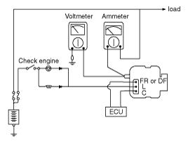
The charging system included a battery, an alternator with a built-in
regulator, and the charging indicator light and wire.
The Alternator has eight built-in diodes, each rectifying AC curre ...
The Alternator has eight built-in diodes, each rectifying AC current to
DC current.
Therefore, DC current appears at alternator "B" terminal.
In addition, the charging voltage ...
See also:
Cylinder Head Cover Components
1. Cylinder head cover
2. Cylinder head cover gasket
...
Tightening Torques
Item
kgf.m
N.m
lb-ft
Positive crankcase ventilation valve installation
0.2 ~ 0.3
1.96 ~ 2.94
1.45 ~ 2.17
Canister install ...
Installation
1.
Install in the reverse order of removal.
A.
...


 Description
 Alternator Description