 Kia Forte: Oil Pump Unit (OPU) Connector
Second generation YD (2014-2018) / Kia Forte TD 2014-2018 Service Manual / Engine Control / Fuel System / ISG (Idle Stop & Go) System / Oil Pump Unit (OPU) Connector
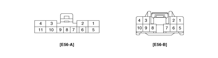
| Opu Connector Terminal Function |
| E56-A |
E56-B |
||
| Pin No. |
Description |
Pin No. |
Description |
| 1 |
Motor power(W) |
1 |
CAN communication (High) |
| 2 |
Motor power(V) |
2 |
CAN communication (Low) |
| 3 |
Hall sensor(Ground) |
3 |
- |
| 4 |
Ground |
4 |
- |
| 5 |
Motor power(U) |
5 |
- |
| 6 |
Shield ground |
6 |
- |
| 7 |
Hall sensor signal input (W) |
7 |
- |
| 8 |
Hall sensor signal input (V) |
8 |
- |
| 9 |
Hall sensor signal input (U) |
9 |
Ignition ON / Start |
| 10 |
Hall sensor power |
10 |
- |
| 11 |
Battery voltage |
|
|
 Electric Oil Pump Installation
1.
Install in the reverse of removal.
...

See also:
Manifold Absolute Pressure Sensor (MAPS) Installation
ŌĆó
Install the component with the specified torques.
ŌĆó
...
ESC Control Module Installation
1.
Install in the reverse order of removal.
2.
Tighten the HECU mounting bolts and nuts to the specified torque.
3.
...
Heater Core Replacement
1.
Disconnect the negative (-) battery terminal.
2.
Remove the heater and blower assembly.
(Refer to Heater -"Heater Unit")
...
Categories
- Home
- Kia Forte BD 2019-2026 Owners Manual
- Kia Forte BD 2019-2026 Service Manual
- First Generation
- Second generation
- Kia Forte TD 2014-2018 Owners Manual
- Kia Forte TD 2014-2018 Service Manual

Copyright ® www.kifomanual.com 2014-2026