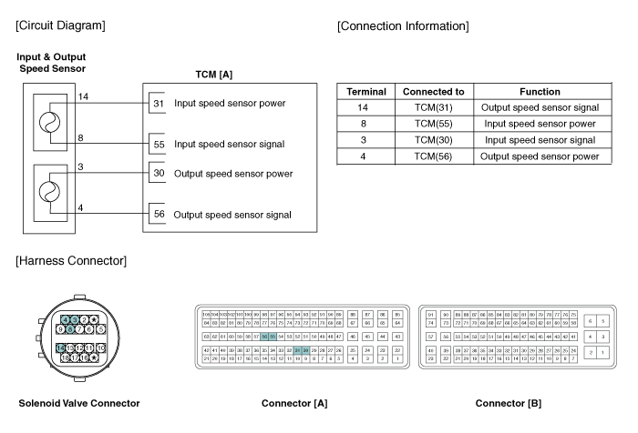
 Kia Forte: Output Speed Sensor Circuit Diagram
Second generation YD (2014-2018) / Kia Forte TD 2014-2018 Service Manual / Automatic Transaxle System / Automatic Transaxle Control System / Output Speed Sensor Circuit Diagram

 Output Speed Sensor Specifications
▷ Type: Hall effect sensor
Operation condition [°C(°F)]
((-)40 ~ 150)) -40 ~ 302
Air gap(mm)in.
(1.1 ~ 1.55)
0.043 ~ 0.061
Output voltage
...
 Output Speed Sensor Signal Waveform
Fig 1) Input/Output speed sensor at low speed
Fig 2) Input/Output speed sensor at high speed ...
See also:
AGM Battery Specification
Item
Specification
Model type
AGM 70L-DIN
Capa ticy [20HR / 5HR] (AH)
70/56
Cold Cranking Amperage (A)
760 (SAE) / 610 (EN)
...
Multimedia Jack Description
The multimedia jack on the console upper cover is for customers who like
to listen to external portable music players like the MP3, iPod and etc., through
the vehicle's sound system when ...
2. TCM Terminal Function
Connector [A]
Pin
Description
Pin
Description
1
-
54
-
2
Line pressure control solenoid valve (LINE_VFS)
55 ...
Copyright © www.kifomanual.com 2014-2025
