 Kia Forte: TJ Joint Components
Second generation YD (2014-2018) / Kia Forte TD 2014-2018 Service Manual / Driveshaft and axle / Driveshaft Assembly / TJ Joint Components
| [LH] |
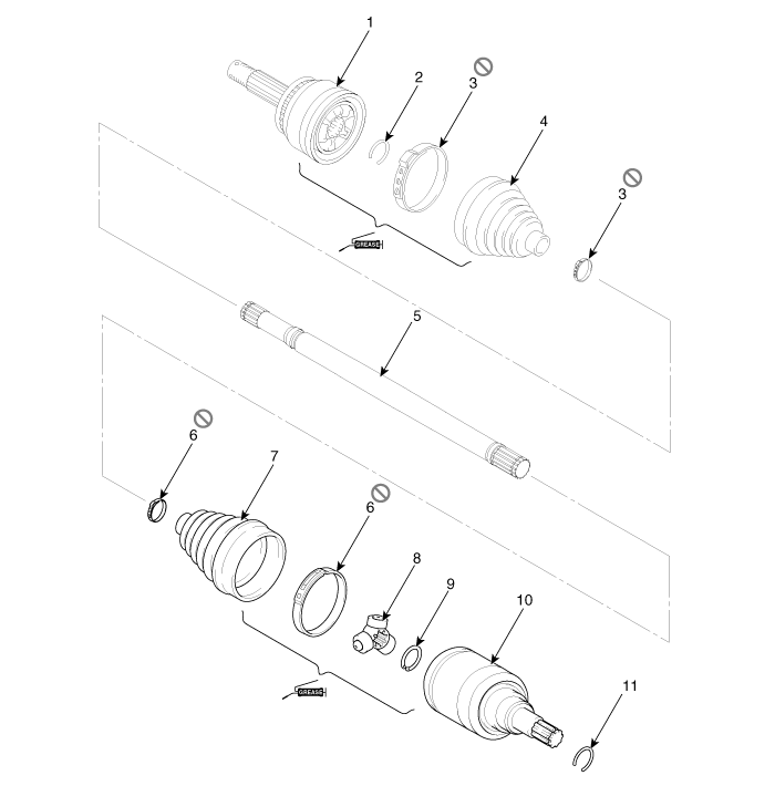
| 1. BJ assembly 2. BJ circlip 3. BJ boot band 4. BJ boot |
5. Shaft 6. TJ boot band 7. TJ boot 8. Spider assembly |
9. Snap ring 10. TJ case 11. Snap ring |
| [RH] |
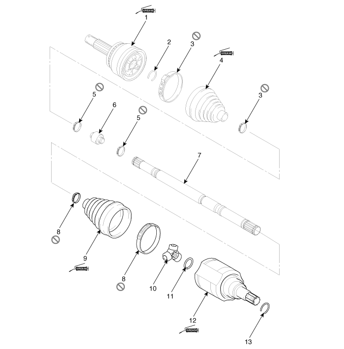
| 1. BJ assembly 2. Circlip 3. BJ boot band 4. BJ boot |
5. Dynamic damper band 6. Dynamic damper 7. Shaft 8. TJ boot band |
9. TJ boot 10. Spider assembly 11. Snap ring 12. TJ case |
13. Circlip |
 Front Driveshaft Replacement
1.
Loosen the wheel nuts slightly.
Raise the vehicle, and make sure it is securely supported.
2.
Remove the front wheel and tire (A ...
 TJ Joint Replacement
ŌĆó
Special grease must be applied to the driveshaft joint.
Do not substitute with anoth ...
See also:
Rear Package Tray Trim Replacement
(4Door)
ŌĆó
Put on gloves to protect your hands.
...
Ignition Coil Installation
1.
Install in the reverse order of removal.
Ignition coil installation bolts:
9.8 ~ 11.8 N.m (1.0 ~ 1.2 kgf.m, 7.2 ~ 8.7 Ib-ft)
...
Crankshaft Position Sensor (CKPS) Removal
1.
Turn the ignition switch OFF and disconnect the battery negative
(-) cable.
2.
Disconnect the crankshaft position sensor connector (A) ...
Categories
- Home
- Kia Forte BD 2019-2026 Owners Manual
- Kia Forte BD 2019-2026 Service Manual
- First Generation
- Second generation
- Kia Forte TD 2014-2018 Owners Manual
- Kia Forte TD 2014-2018 Service Manual

Copyright ® www.kifomanual.com 2014-2026